Pluggable I/O product type
Cage, Connector or Cage+Connector. The cage gives mounting, guidance and shielding; the SFP receptacle carries the contacts; a cage assembly combines both.
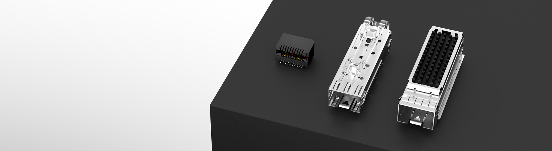
I/O Connector products
Select host-side pluggable I/O components for switches and networking equipment: cages, PCB receptacle connectors, or cage-and-connector assemblies. Browse SFP/SFP+, SFP28 and QSFP families, then compare port layout, mounting, light-pipe and thermal options. These are host-side components, not optical transceivers.
Part number search & selector
The table uses the current English-site product records, published selection fields and part-specific technical-file links.
* Frozen Image and Part Number columns · drag horizontally to review all specifications
| Image | Datasheet | Compare | Downloads |
Pluggable I/O product type
|
Overall dimensions
|
Data Rate (Max) (Gb/s)
|
Installation Type
|
Ports
|
Included Lightpipe
|
Heat dissipation
|
Connector Gold Plated
|
Nickel Plated Shell
|
Sample |
|---|
| Image | Part number | Datasheet | Compare | Downloads | Pluggable I/O product type | Overall dimensions | Data Rate (Max) (Gb/s) | Installation Type | Ports | Included Lightpipe | Heat dissipation | Connector Gold Plated | Nickel Plated Shell | Sample |
|---|---|---|---|---|---|---|---|---|---|---|---|---|---|---|
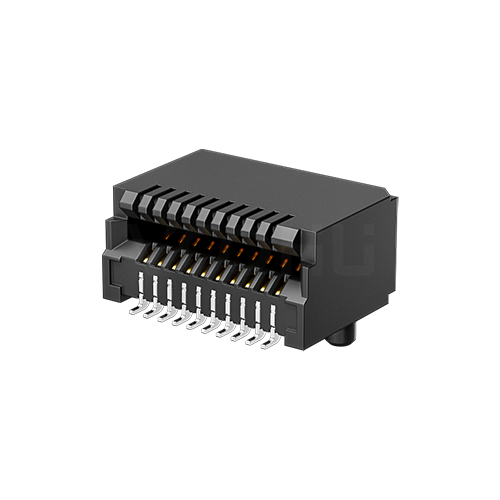 |
WH290Z019D0S01 | SPEC | Connector | SFP+ | 10G | Solder | 1 x 1 | NONE | - | 15U | Ni 50U |
|
||
 |
WH81-151-Y0002-1 | SPEC | Connector | SFP+ | 10G | - | 1 x 1 | NONE | - | 15U | None |
|
||
 |
WH290W119D0S03 | SPEC | Connector | SFP+ | 10G | - | 1 x 1 | NONE | - | 30U | None |
|
Broaden the selected filters or clear the current search.
Is this another brand's part number? Find the VOOHU replacement →
Product family quick links
Counts by series come from the current records, from SFP and SFP+ through SFP28 to the QSFP family.
How to select
Work from the module standard to the board: which part you are buying, which family and port array, how it mounts, and which thermal and light-pipe features the system needs.
Decide between an SFP cage alone, a PCB receptacle alone or a cage assembly, then the family, from SFP (5G) through SFP+ and SFP28 up to 400G QSFP-DD and QSFP112.
Match a 1×N ganged or 2×N stacked array to the panel, then choose press-fit or solder tails for the board process.
Confirm light pipes, heat sink or vented top, module power, airflow and chassis grounding for every port of the SFP cage.
Check fit, signal integrity at the lane rate and thermal margin against the part drawings and samples before production sourcing.
Key selection parameters
The selector fields describe host-side hardware. Module behaviour and the system data rate are set by the transceiver, the PHY and the board, not by an SFP cage alone.
Cage, Connector or Cage+Connector. The cage gives mounting, guidance and shielding; the SFP receptacle carries the contacts; a cage assembly combines both.
SFP through QSFP112 name interface families, not sizes. Take SFP cage dimensions in millimetres from the part drawing.
The data rate column (5G to 400G) is the family class, not a link guarantee. Ports read rows × columns, from 1 x 1 up to 2 x 12.
Press-Fit parts need the specified plated holes and press tooling. Solder parts, such as some SFP28 cage versions, need a confirmed process; check SMT or through-hole tails in the drawing.
Light pipe layout, vented holes or heat sink, contact gold (15U or 30U) and nickel shell plating are listed per part. Confirm what each part number includes.
Product family comparison
Rows group the range by product type. Combined SFP cage connector assemblies are the largest group and are listed as press-fit stacked 2×N arrays; cages alone cover single, ganged 1×N and 2×1 layouts, and PCB connectors are 1×1 parts.
Return to the selector ↑| Pluggable I/O product type | Parts | Overall dimensions | Data Rate (Max) (Gb/s) | Installation Type | Ports | Included Lightpipe | Heat dissipation | Connector Gold Plated | Nickel Plated Shell | Action |
|---|---|---|---|---|---|---|---|---|---|---|
| Cage | 77 | SFP, SFP+, SFP28, QSFP/QSFP+, QSFP28, QSFPDD | 5G, 10G, 25G, 40G, 100G, 400G | Solder, Press-Fit, Not specified | 1 x 1, 1 x 2, 1 x 4, 1 x 5, 1 x 6, 2 x 1 | NONE, ○ ○, △ ▽, ○, ○○○○, Not specified | Heat dissipation holes, Heat Sink, Not specified | 30U, None, Not specified | Ni 30U, Ni 30U~50U, Ni 30U~80U, None, Not specified | Filter → |
| Connector | 14 | SFP, SFP+, SFP28, QSFP/QSFP+, QSFP28, QSFPDD, QSFP56, QSFP112 | 5G, 10G, 25G, 40G, 100G, 200G, 400G | Solder, -, Not specified | 1 x 1 | NONE | -, Not specified | 15U, 30U, None | Ni 50U, None | Filter → |
| Cage+Connector | 143 | SFP, SFP+, SFP28, QSFP/QSFP+, QSFP28, QSFP56, Not specified | 5G, 10G, 25G, 40G, 100G, 200G | Press-Fit | 2 x 1, 2 x 2, 2 x 3, 2 x 4, 2 x 5, 2 x 6, 2 x 8, 2 x 12 | NONE, ○ ○, ▽△▽△, △ ▽△▽, ▽ △, ▽△, △▽, △ ▽, △○▽, ▽○△, △□▽, ▽□△, 口△▽口 | Heat dissipation holes, Heat Sink | 15U, 30U, None | Ni 30U, Ni 50U, None | Filter → |
Technical performance & application fit
On a switch or router the SFP hardware sets port density, front-panel layout and the thermal path. Send the module family, port count, board stack-up and airflow so the review covers the whole interface.
Downloads & technical resources
Type a full or partial part number to open its datasheet or 3D model. Board footprints are not listed as separate files, so take the PCB pattern from the drawing or ask us for it.
Showing representative available file sets. Search to find a specific SKU.
VOOHU’s published product content is reviewed by its engineering team. Specifications, downloads and technical support information are tied to specific part numbers, so you can verify them before requesting samples or a quotation.
Category overview
Most of the confusion in this category comes from three separate things being encoded in one part description.
Discuss a new design
Contact FAE for a replacement assessment.
Already have a part number? Request samples or a quote.
SFP, SFP+ and SFP28 share a mechanical form factor and differ in the data rate they are qualified for. The QSFP line (QSFP+, QSFP28, QSFP56 and QSFP112) is a physically larger four-lane form factor, and QSFP-DD adds a second row of contacts for eight lanes. A mechanical fit between two of these proves nothing about signal integrity at your rate.
Lane rates explain the ladder. SFP+ runs one 10G NRZ lane and SFP28 one 25G NRZ lane; QSFP28 uses four 25G NRZ lanes for 100G, QSFP56 four 50G PAM4 lanes for 200G, and QSFP-DD reaches 400G with eight 50G PAM4 lanes, as QSFP112 does with four 100G lanes. The documents behind them include SFF-8431 and SFF-8432 for SFP+, SFF-8436 and SFF-8679 for QSFP+, SFF-8665 for QSFP28 and a separate MSA for QSFP-DD.
A figure such as 1x1, 1x4, 2x1 or 2x5 describes how the ports are arranged, rows first and columns second. A ganged row and a stacked column with the same port count need completely different panel cutouts and board footprints, so read it before the panel is laid out.
A 1x4 ganged SFP cage puts four ports side by side in one shell, while a 2x1 SFP cage is the smallest stacked cage, with two ports one above the other. On this page the stacked arrays are mostly cage-and-connector assemblies, while cages alone come as single ports or as a ganged cage of up to six ports.
Parts are supplied as a cage alone, a PCB receptacle alone, or the two together. On top of that sit press-fit or solder tails, optional heat sinks and light pipes, and a stated contact plating thickness. Each affects the assembly process and long-term contact reliability, so specify them all.
An SFP connector and cage bought separately must be drawn for each other: the SFP connector footprint sits inside the cage pattern on the board. On many designs the SMT connector is reflowed first and the press-fit cage is pressed in afterwards, so agree the process order with your assembler.
FAQ & related guides
Answers on cages, pinouts, interchangeability, press-fit and heat sinks. Limits for each SFP connector or cage part number come from its own datasheet.
A cage provides mounting, module guidance and shielding; the SFP host connector, a PCB receptacle, provides the electrical interface; a cage assembly combines them. Buying a cage does not automatically include a connector or heat sink, so check what each part number covers.
No. This page covers host-side pluggable I/O connector hardware: the transceiver cage, the receptacle and combined assemblies. The optical or copper module is a separate product, and wavelength or reach are module specifications, not connector ones.
The SFP and SFP+ host connector has 20 contacts. Signal assignment comes from the MSA documents (SFF-8431 for SFP+), and the 0.8 mm card-edge interface is described in SFF-8083. Use the part drawing for contact numbering, holes and viewing direction rather than a generic pinout.
A QSFP host connector has 38 contacts for four lanes plus management signals, and a QSFP-DD connector adds a second row for 76 contacts and eight lanes. On a QSFP cage connector assembly the receptacle is already located in the cage, but numbering and footprint still come from the part drawing.
Not on appearance alone. An SFP28 connector and an SFP+ connector can share an outline while being qualified for different lane rates. Review interface requirements, contact design, electrical performance, port layout and PCB design, and assess any replacement at part and system level.
Choose for the PCB hole construction, assembly equipment, process window and rework needs. An SFP cage press-fit footprint needs the specified plated holes and board support, and SFP+ cage press-fit holes usually differ from solder-tail holes. Solder parts need a confirmed soldering process, not an assumed reflow capability.
It depends on module power, airflow and ambient temperature. Lower-power SFP and SFP+ modules often manage with a vented cage, while higher-power QSFP modules call for a heat sink, as on the QSFP-DD cage versions that list one. Validate thermal margin in the real chassis and confirm heat-sink inclusion and retention for the selected part.
For a known part, give quantity, accessories, project stage and timing. For a replacement, add the existing drawings and PCB and panel constraints. If you are qualifying an SFP cage manufacturer, ask for the drawing revision and plating specification; VOOHU builds its connectors in its own factory in Dongguan.
Engineer support
Send the candidate part number and the condition you need reviewed. Sample support can be added after the selection is clear; commercial questions may be discussed in the same engineering conversation.
Include the document revision
Temperature, isolation voltage and PoE current basis
Pin count, pitch and spacing between pin rows
To help prioritize samples and evaluation
When you need candidates and a comparison of differences
Engineering review identifies candidate parts and explains the differences.
From the selector or engineering review
Prototyping / pilot build / production
Specify sample and production timing separately
Compliance documents, material declarations or third-party reports
Samples are available for evaluation, and selected parts are free of charge. Our FAE team will be glad to confirm the options for your project. Sales will respond on business days.