TOPIC

LAN Transformers

Technical articles and news about LAN Transformers, newest first.

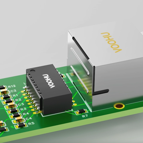
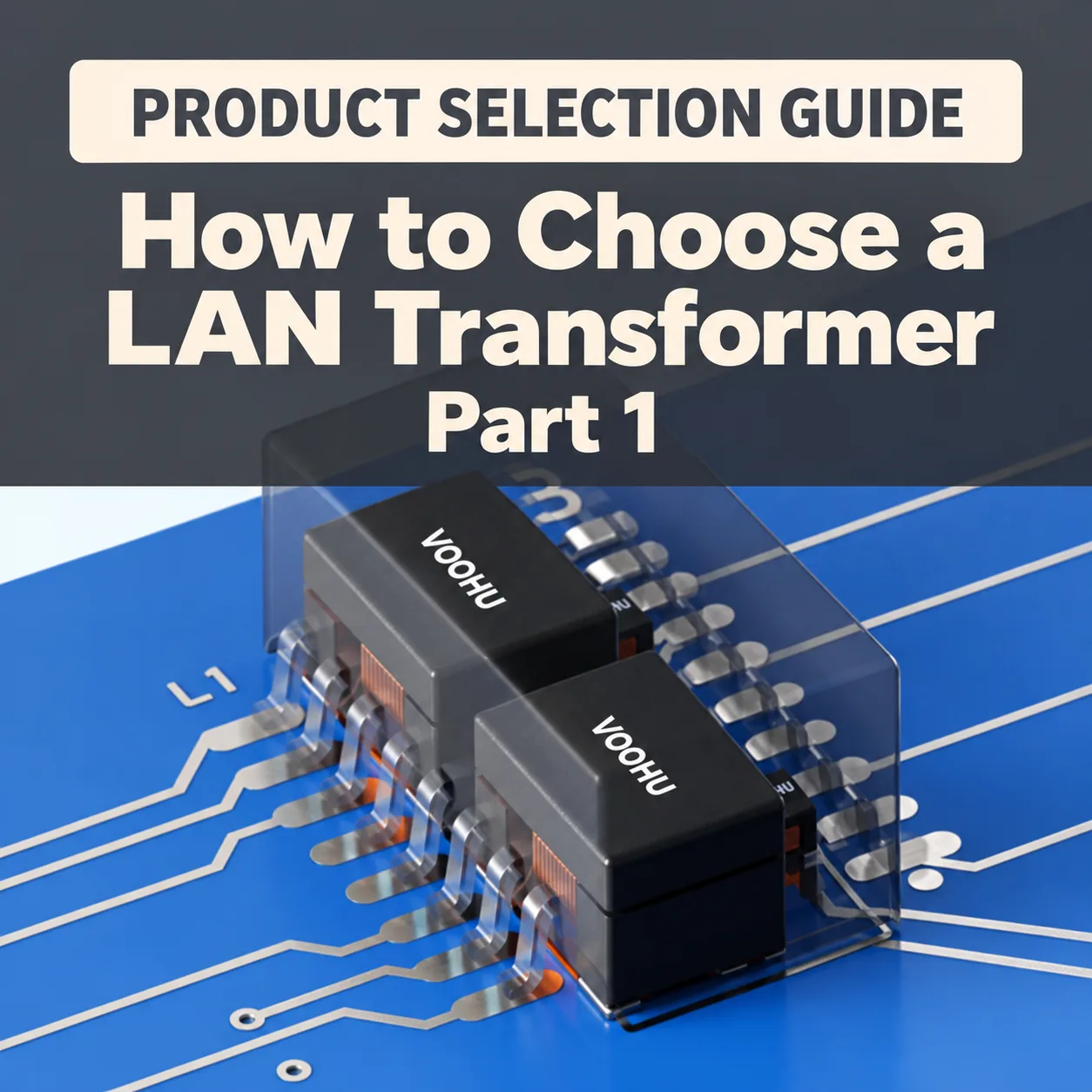
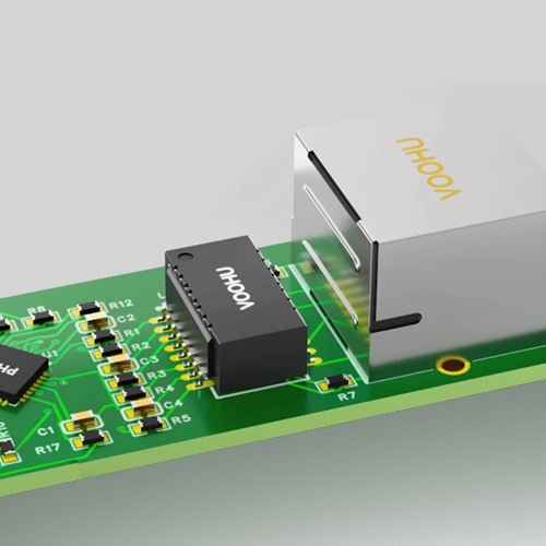
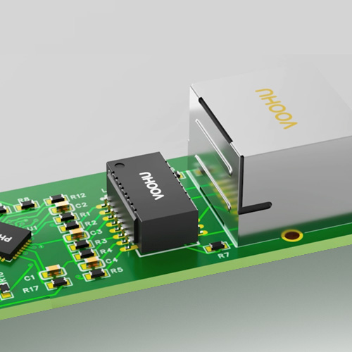
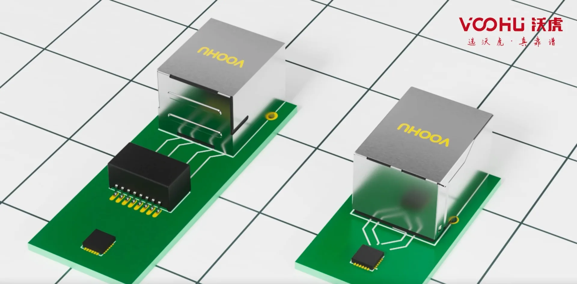
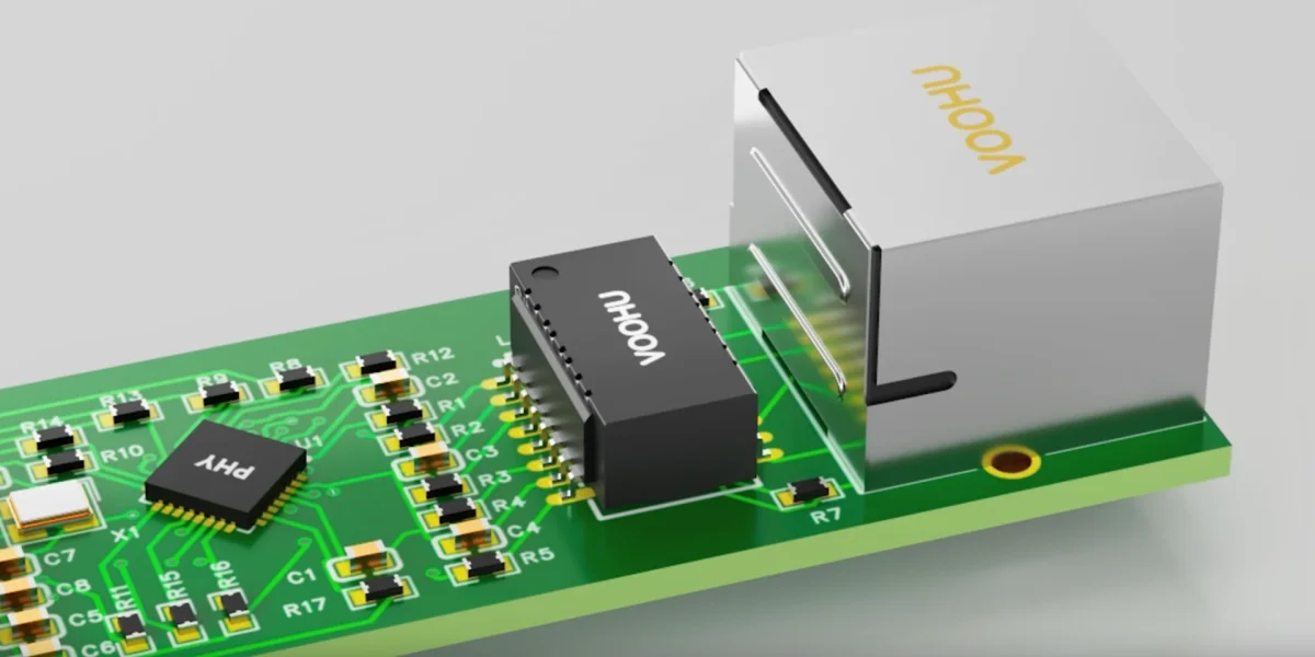
A LAN transformer (Ethernet magnetics) isolates and matches the Ethernet port. In essence it is a set of 1CT:1CT high-frequency isolation transformers plus common-mode chokes: it couples the PHY differential signals to the cable side while providing isolation and common-mode noise suppression.

Because it affects both signal integrity and EMC, selection cannot stop at data rate and package. Narrow down the series by data rate, PoE, PHY drive type and package first, then read OCL, insertion loss, return loss, common-mode rejection and DCR in the datasheet, and finally set the isolation rating by the operating environment.

How to choose

  1. 01Pick the series by data rate

    10/100, Gigabit, 2.5G / 5G and 10G LAN transformers have different parameters; start from the PHY data rate.

  2. 02Confirm the PHY drive type

    For voltage-mode PHYs the center tap goes to ground through a capacitor; for current-mode PHYs it goes to the PHY supply. Follow the PHY reference circuit for the turns ratio, which is 1CT:1CT in most cases.

  3. 03Check for PoE

    With PoE, look at OCL under DC bias and at the PoE current rating, so the core does not saturate and the port does not overheat at full load.

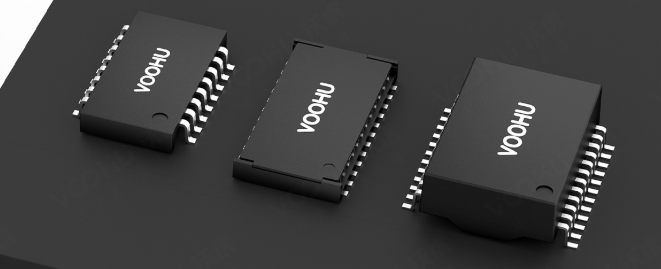
  4. 04Set package and isolation rating

    DIP or SMD; single, dual or quad port; pin count, pitch and height against the PCB footprint. Choose the isolation voltage for indoor, industrial or outdoor use.

Key parameters

ParameterWhat it tells youTypical Gigabit requirement
Open-circuit inductance (OCL)Low-frequency response; under PoE, check the value with DC bias applied≥ 350 µH at 100 kHz, 100 mV, 8 mA DC bias
Insertion lossHow much signal is lost through the transformer; it directly reduces SNR marginNo worse than about −1.0 dB from 1 to 100 MHz
Return lossHow well the port impedance matches 100 Ω≥ 16–18 dB from 1 to 30 MHz, relaxed gradually at higher frequencies
Common-mode rejection (CMRR)Suppression of common-mode noise, related to radiated emissionsHigher is better; compare the curves by frequency band
DC resistance (DCR)Voltage drop and temperature rise under PoE currentAbout ≤ 0.9 Ω per winding
Isolation voltageInsulation between the chip side and the cable side1500 Vrms for 60 s (IEEE 802.3 baseline); 2000–3000 Vrms for industrial and outdoor ports

Values are typical requirements for Gigabit LAN transformers; the datasheet of each part number governs.

FAQ

Q1How much OCL do I need, and does PoE change it?

The usual minimum for Gigabit LAN transformers is 350 µH at 100 kHz, 100 mV. With PoE you must check OCL under DC bias: the DC current lowers the inductance and can saturate the core, so choose a part rated for your PoE current.

Q2Is 1500 Vrms isolation enough?

For ordinary indoor ports, the IEEE 802.3 baseline of 1500 Vrms for 60 seconds is enough. For PoE, noisy industrial sites, long cables or outdoor ports, go to 2000–3000 Vrms and add proper surge protection.

Q31:1 turns ratio or something else?

Follow the PHY datasheet. Most PHYs use 1CT:1CT; a few require a different ratio, and the wrong one causes amplitude mismatch and link negotiation problems.

Q4If the port fails Hi-Pot, is the LAN transformer to blame?

Usually not. A common cause is the center-tap capacitor across the isolation barrier being rated too low, or too little creepage on the PCB. Replace that capacitor with one rated 2 kV or higher and test again.

All LAN Transformers articles

40 articles

Need samples or selection support?

Tell us your interface, speed and package requirements. Our FAE team can suggest suitable parts and help check the design.

Phone+86 133 5804 1040VOOHU WhatsApp QR codeScan with your phone to chat on WhatsAppMon–Fri 8:30–18:00 (UTC+8)Emailvoohu@voohuele.com
SUBSCRIBE

Subscribe to VOOHU technical articles

Get new articles in your inbox. Unsubscribe at any time.

By subscribing you agree to our Privacy Policy