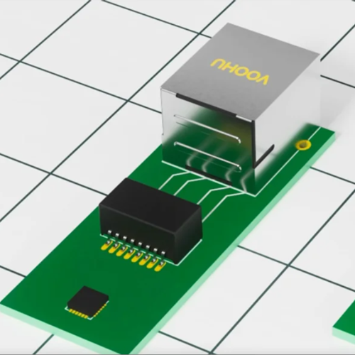
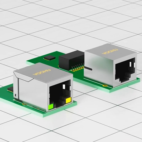
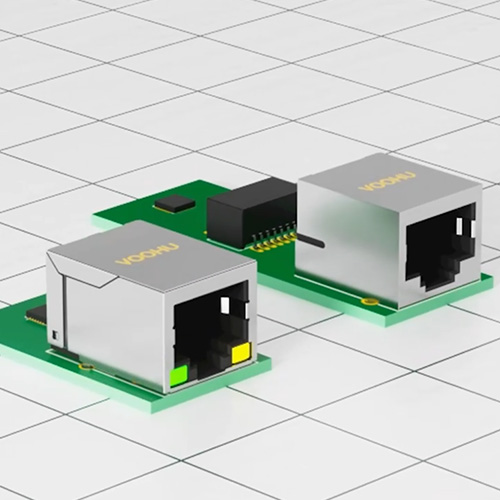
An RJ45 jack is the interface closest to the outside world, and usually the first one to be locked in on a board. It is more than a socket for a cable: whether the magnetics are integrated, whether the latch faces up or down, how the shield is grounded and how the LEDs are wired all affect EMC, ESD, assembly and later part changes.
A practical order: set the electrical requirements from data rate and PoE, then choose integrated or discrete magnetics and the mechanics (port count, latch direction, mounting height), and finally check LEDs, shield grounding and protection together. Below are the selection steps, the key parameters and the questions engineers ask most.
ParameterWhat to check
Data rate and ports10/100, 1000, 2.5G and up; single port, multi-port or stacked
Integrated magneticsWhether the LAN transformer and common-mode choke are built in; for PoE versions, check the rated current
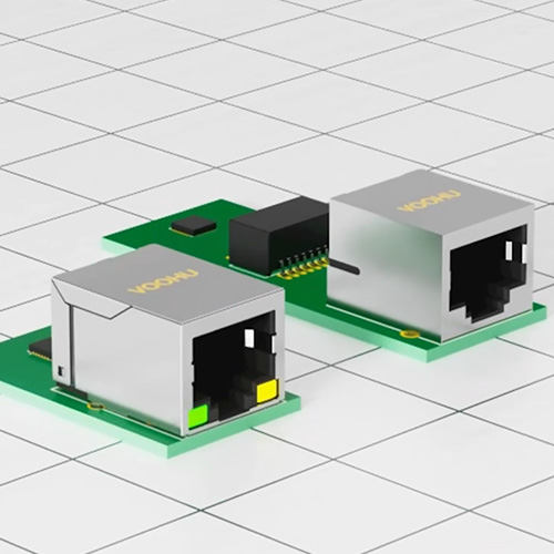
Latch directionTab up or tab down; changing it mirrors the contact order and the LED positions
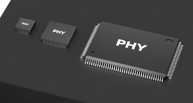
LEDsColor (such as green / yellow), left or right position and polarity, matched to the PHY LED drive
Shielding and groundingShield can, ground pins and EMI fingers; the shield must be bonded to chassis ground
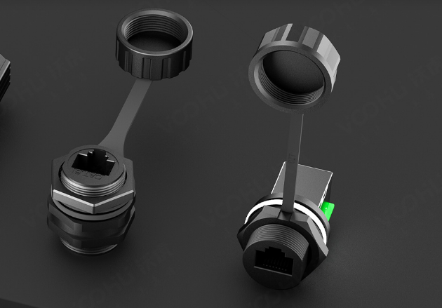
Isolation voltageIntegrated-magnetics versions are commonly 1500 Vrms (the IEEE 802.3 baseline); higher ratings are available for industrial and outdoor ports
Mounting and profileHorizontal or vertical, sink-in (board cutout) or low profile; height against the panel opening





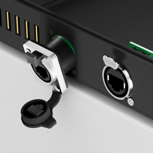

![[New Product Recommendation] CAT6A 10 Gigabit Waterproof RJ45 Coupler Male and Female](/upload/image/20260717/4694ba2c3b52b9d273512e3777f53f84.jpg)