



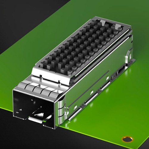
SFP Module Running Hot? Vented vs. Heat-Sink Cages and the Lower Port of a 2×1 Stack
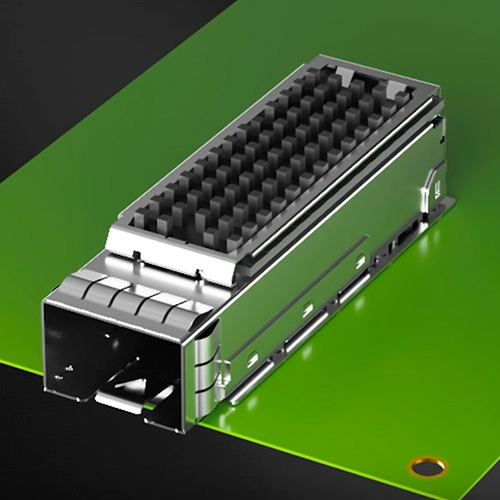
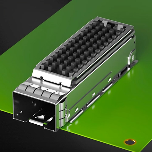
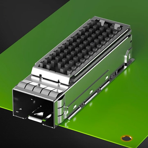
SFP module temperature alarms? Only 13 of 205 VOOHU SFP, SFP+ and SFP28 cages carry a heat sink, and all are single-row 1×N; none of the 135 stacked 2×N parts d
Technical articles and news about SFP Connectors, newest first.
SFP connectors (the cage and the board-side connector) are where optical and copper modules plug into the equipment. SFP, SFP+ and SFP28 share the same form factor and pin definition and usually correspond to 1G, 10G and 25G; the QSFP family covers multi-lane 40G, 100G and above.
A module that fits is only the starting point. Consider data rate, port layout (1×N single row or 2×N stacked), press-fit or soldered, light pipes and indicators, cooling and the panel opening together, and verify insertion, LED positions, temperature rise and EMC in the real enclosure.
SFP, SFP+, SFP28 or QSFP. When a port moves from 10G to 25G, confirm the host SerDes and channel loss too; a cage cannot replace system validation.
1×1, 1×N single row or 2×N stacked; a cage only, or a cage plus connector assembly, checked against the BOM and assembly route.
Press-fit needs tight control of board hole tolerances; follow the current mechanical drawing. Evaluate press tools and fixtures separately for single-port and multi-port cages.
No light, light pipes or outer dual lights, matched to how the panel shows status; a vented cage or a heat sink, with temperature rise verified against module power and airflow direction.
They share the form factor and pin definition but run at different rates. Fitting mechanically is only the start: when changing the data rate, confirm the host SerDes, the differential channel and system validation, and follow the drawing of the current part number.
Not necessarily. First read the module DDM temperature and alarm thresholds to confirm it really overheats. A heat sink needs airflow along its fins, and the lower port of a stacked cage is the hardest to cool, so start from the airflow and the port layout.
Check the board holes, board thickness and hole plating against the current drawing, then the press fixture support and pressing sequence; record height and coplanarity before and after pressing, then recheck with the real panel installed.
First confirm the PCB LEDs work without the light pipes installed, then check whether the light pipes are reversed, whether their input ends line up with the LEDs, and whether the panel pushes them out of position.
SFP module temperature alarms? Only 13 of 205 VOOHU SFP, SFP+ and SFP28 cages carry a heat sink, and all are single-row 1×N; none of the 135 stacked 2×N parts d
A practical four-layer check for SFP presence, 3.3 V power, I²C management and board-side connector contact.
A practical way to separate SFP link drops, module loss and board resets during ESD testing, then improve the cage, bezel, return path and protection design.
Learn how to choose a no-light, 1×4 light-pipe, or 2×6 outer-dual-light SFP cage, prevent light leakage and panel misalignment, and match VOOHU SFP+ and SFP28 p
What should I do if the SFP optical module cannot be pulled out? The most dangerous thing on site is not to temporarily stop the machine, but to continue to sha
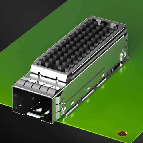
Starting from module cross-testing, terminal contact, SMD solder joints, mechanical positioning and high-speed channels, the board-level inspection and mass pro
Starting from the public on-shelf material numbers of SFP+ and SFP28 optical cages, we sort out the board-level verification boundaries of Press-Fit holes and t
VOOHU WH291Z02SD0S02 replaces Pulse SFPPCAGE011-L, SFP+ 1×1 cage core parameter comparison.
Comparison of SFP 1×1 cage parameters between VOOHU WH191R02SD0S02 and Pulse SFPCAGE002-L and considerations for alternative selection.
Comparison of SFP+ 1×4 cage parameters between VOOHU WH294T459D0S02 and Amphenol U77-A461M-X081 and considerations for alternative selection.
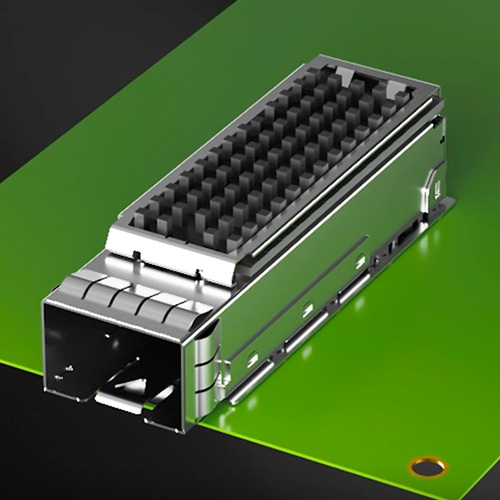
VOOHU WH291Z02SD0S02 replaces the obsolete Molex 74754-0101 — a single-port SFP+ 1×1 EMI cage. Key-parameter comparison of housing material, EMI bezel gasket, p
VOOHU WH191R02SD0S02 replaces Molex 74737-0009: SFP 1x1 one-piece press-fit EMI cage, key-parameter comparison.
Tell us your interface, speed and package requirements. Our FAE team can suggest suitable parts and help check the design.
 Scan with your phone to chat on WhatsAppMon–Fri 8:30–18:00 (UTC+8)Emailvoohu@voohuele.com
Get new articles in your inbox. Unsubscribe at any time.




