Communication and interconnect · Application solutions

Ethernet Switching

Multi-port switching and PoE switches. Part of the "Communication and interconnect" group, which runs from PHYs and switching to industrial buses and pairs each chip with a matching port design.

Ethernet Switching solution icon

Typical application circuits

Circuit approaches and matching VOOHU parts, organized by application scenario.

SW-01

10/100BASE-TX multi-port switch reference board

Start from the switch chip. Choose 10/100 Mbps magnetics, interfaces, power and clocking for the port count, then validate forwarding and configuration.

  1. Switch chip
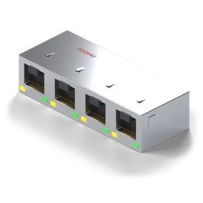
  2. Multi-port magnetics and interfaces
  3. Forwarding and configuration validation
  • Data communications
  • Industrial control

Core chips (vendor documentation)

  • JL5104C-NIEthernet switch chip

    10/100 Mbps Ethernet switch chip, NI variant of the JL5104 series, 3+1 interface configuration.

    View the JL5104 series →

Design checklist

  • Do not substitute a single-port PHY reference schematic for a switch design.
  • Every port and every configuration setting must be traceable.
  • Check the port and uplink definitions, configuration pins and reset.
  • Complete forwarding tests and thermal tests.
SW-02

Gigabit multi-port switch reference board

Design each MDI channel, the magnetics and RJ45s, power and uplink around the Gigabit switch chip. Choose the temperature grade for the target environment.

  1. Gigabit switch chip
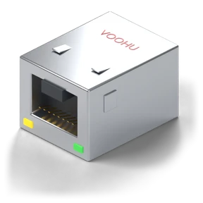
  2. Multi-port magnetics and RJ45
  3. Switching and thermal validation
  • Data communications
  • Security and surveillance

Core chips (vendor documentation)

  • JL6105-NCEthernet switch chip

    5-port Gigabit Ethernet switch chip, QFN88 package, temperature range 0–70°C.

    View the JL6105 series →

Matching VOOHU parts

Design checklist

  • The JL6105-NC temperature range is 0–70°C. Do not treat it as an industrial-grade part.
  • Confirm the management and configuration capabilities item by item.
  • Check port mapping, clocking, power sequencing and registers.
  • Record throughput and temperature-rise test results.
SW-03

PoE switch combined reference design

The switch chip forwards data. The PSE controller injects power into each port through the magnetics and RJ45. Plan one power budget that covers both.

  1. Switch data path
  2. Magnetics/RJ45 and PSE power injection
  3. Powered devices and power management
  • Industrial control
  • Data communications

Core chips (vendor documentation)

Matching VOOHU parts

Design checklist

  • PoE port definitions and the power budget must be calculable line by line.
  • Validate the switch chip and PSE controller pairing first.
  • Check the system power supply and power policy against the port count and power class.
  • Check host control and heat dissipation, and run data and power interoperability tests.
SW-04

Switch chip configuration and software support

After power-on reset, complete the switch chip's register configuration, then run link diagnostics and version management. Available software features depend on what the chip vendor supports.

  1. Power/reset startup
  2. Configuration and registers
  3. Link diagnostics and version management
  • Industrial control
  • Data communications

Core chips (vendor documentation)

  • JL5104C-NIEthernet switch chip

    10/100 Mbps Ethernet switch chip, NI variant of the JL5104 series, 3+1 interface configuration.

    View the JL5104 series →
  • JL6105-NCEthernet switch chip

    5-port Gigabit Ethernet switch chip, QFN88 package, temperature range 0–70°C.

    View the JL6105 series →

Design checklist

  • Rely only on software features that the vendor documentation explicitly supports.
  • Do not use an unmanaged chip as a managed switch chip.
  • Initialization scripts must match the chip revision.
  • On platforms that need an SDK, develop with the vendor SDK and its user guide.

Chip part numbers are taken from the vendors' public documentation and are for selection reference only. Check matching VOOHU parts against your project parameters before use.

Standard reference designs for this solution area are being prepared and will be listed on this page once published. For circuit and part selection support, contact a VOOHU FAE.

Need help selecting parts for your project?

Send the chip model, interface data rate, and power and protection requirements to a VOOHU FAE to check the peripheral parts against a reference design.

Contact an FAE →