Communication and interconnect · Application solutions

RS-485 / RS-422

Industrial serial buses and isolated interfaces. Part of the "Communication and interconnect" group, which runs from PHYs and switching to industrial buses and pairs each chip with a matching port design.

RS-485 / RS-422 solution icon

Typical application circuits

Circuit approaches and matching VOOHU parts, organized by application scenario.

RS-01

Half-duplex RS-485 transceiver circuit

The MCU UART connects to a 2-wire RS-485 bus through a half-duplex transceiver. The design focuses on direction control, fail-safe, termination and biasing.

  1. MCU UART
  2. Half-duplex transceiver
  3. 2-wire RS-485 bus
  • Industrial control
  • Power grid
  • PV and energy storage

Core chips (vendor documentation)

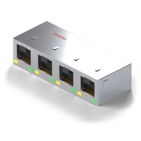
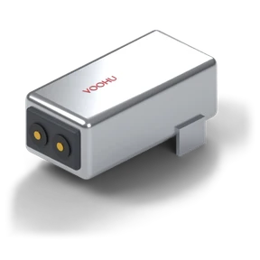
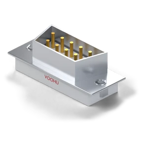
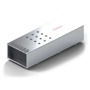
Matching VOOHU parts

Design checklist

  • Do not derive the maximum cable length from the chip's maximum data rate. Determine it by testing with the cable and a prototype.
  • Check the node count and bias conditions based on unit loads.
  • Check the DE and RE direction-switching timing.
  • Confirm that the bus common-mode voltage is within the range the transceiver allows.
RS-02

Full-duplex RS-485 / RS-422 circuit

The MCU UART connects through a full-duplex transceiver to separate transmit and receive differential pairs, forming a full-duplex link.

  1. MCU UART
  2. Full-duplex transceiver
  3. Separate transmit/receive pairs
  • Industrial control
  • Power grid

Core chips (vendor documentation)

Matching VOOHU parts

Design checklist

  • First decide whether the network is built as RS-422 or RS-485, and define its network conditions.
  • Do not reuse the half-duplex wiring diagram.
  • Set the termination positions and wiring definitions by topology and the role of the far end.
  • Check the ground potential difference between the two ends, and run transmit and receive tests.
RS-03

Isolated RS-485 and isolated power supply

Select the isolated RS-485 transceiver and the isolated supply separately, then validate them together on one reference board.

  1. MCU UART
  2. Isolated RS-485 transceiver
  3. Bus; separate isolated supply
  • Industrial control
  • Power grid
  • PV and energy storage

Core chips (vendor documentation)

Matching VOOHU parts

Design checklist

  • Validate at the target data rate.
  • The chip's isolation withstand voltage is not the system's continuous working voltage.
  • Check that the push-pull transformer matches the transceiver supply load.
  • Check creepage distance and isolation capacitance, and run immunity tests.
RS-04

Long-cable RS-485 immunity and protection

For long cables and ground potential differences, place a termination and protection network between the bus and the transceiver. Set its values by receiver margin, common-mode voltage and fault modes.

  1. Long cable and ground potential difference
  2. Termination and protection network
  3. RS-485 transceiver
  • Industrial control
  • Power grid
  • PV and energy storage

Core chips (vendor documentation)

Matching VOOHU parts

Design checklist

  • Waveform and bit-error tests must cover worst-case conditions.
  • Check the bias loading against the actual cable, length and data rate.
  • Calculate the node count from the actual load. Do not treat it as unlimited.
  • Check clamping and the ground potential difference, and run EFT and recovery tests.

Chip part numbers are taken from the vendors' public documentation and are for selection reference only. Check matching VOOHU parts against your project parameters before use.

Standard reference designs for this solution area are being prepared and will be listed on this page once published. For circuit and part selection support, contact a VOOHU FAE.

Need help selecting parts for your project?

Send the chip model, interface data rate, and power and protection requirements to a VOOHU FAE to check the peripheral parts against a reference design.

Contact an FAE →