Communication and interconnect · Application solutions

Single Pair Ethernet (SPE)

T1L, T1S and power over data lines. Part of the "Communication and interconnect" group, which runs from PHYs and switching to industrial buses and pairs each chip with a matching port design.

Single Pair Ethernet (SPE) solution icon

Typical application circuits

Circuit approaches and matching VOOHU parts, organized by application scenario.

SPE-01

10BASE-T1L PHY interface

The host MAC connects to the single-pair cable through a 10BASE-T1L PHY and an MDI coupling network. Fit an SPE connector at the port as needed.

  1. Host MAC
  2. 10BASE-T1L PHY
  3. Coupling network and single-pair cable
  • Industrial control
  • PV and energy storage

Core chips (vendor documentation)

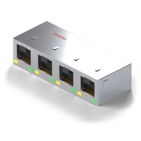
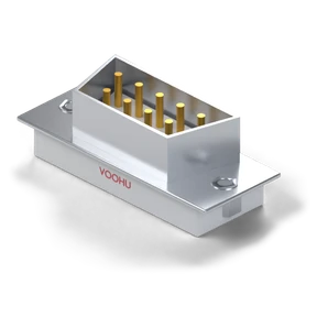
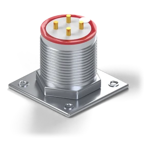
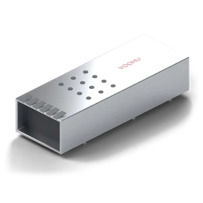
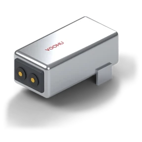
Matching VOOHU parts

Design checklist

  • Check the interface circuit and the connector standard separately.
  • Do not infer the link distance from the connector part number.
  • Check the coupling magnetics, termination and MAC timing against the PHY reference circuit.
  • Check connector mating and the cable, and run interoperability tests.
SPE-02

10BASE-T1S MAC-PHY node

The MCU connects to a 10BASE-T1S MAC-PHY over SPI, and the MAC-PHY joins the multidrop network through a coupling network. This circuit is independent of the T1L circuit.

  1. MCU SPI
  2. 10BASE-T1S MAC-PHY
  3. Coupling and multidrop network
  • Industrial control

Core chips (vendor documentation)

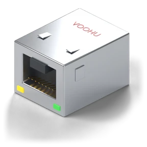
Matching VOOHU parts

Design checklist

  • Define the T1S network conditions and control mode.
  • Do not reuse T1L distances or the T1L magnetics network.
  • Check the host driver, SPI bandwidth and PLCA configuration.
  • Choose coupling parts and connectors for the node topology, and run collision and bit-error tests.
SPE-03

SPE data and PoDL power

Power control and coupling are added on top of the T1L data link to deliver power to the powered end over the single-pair cable. Select the controller and the power magnetics separately.

  1. T1L PHY + power control
  2. Data/power coupling
  3. Single-pair cable and powered end
  • Industrial control
  • PV and energy storage

Core chips (vendor documentation)

Matching VOOHU parts

Design checklist

  • Do not port an RJ45 PoE circuit directly to PoDL.
  • Validate power and data together.
  • Define the PSE and PD roles and the applicable standard.
  • Check the coupling inductors, detection, protection and temperature rise.

Chip part numbers are taken from the vendors' public documentation and are for selection reference only. Check matching VOOHU parts against your project parameters before use.

Standard reference designs for this solution area are being prepared and will be listed on this page once published. For circuit and part selection support, contact a VOOHU FAE.

Need help selecting parts for your project?

Send the chip model, interface data rate, and power and protection requirements to a VOOHU FAE to check the peripheral parts against a reference design.

Contact an FAE →