Ethernet PHY · Reference design collection
Ethernet PHY Reference Designs: 10/100, Gigabit and 10G Port Schematics
These Ethernet PHY reference designs are schematics for the Ethernet port circuit (also called the Ethernet interface circuit, or PHY peripheral circuitry): the circuit that runs from the MDI differential pins of the PHY chip, through a LAN transformer (Ethernet magnetics), an RJ45 with integrated magnetics, or a chip LAN, to the RJ45 cable contacts. This circuit determines whether the link negotiates reliably, whether the port passes EMC and surge tests, and how GND is kept separate from chassis ground (SHIELD).
10/100 Mbps Ethernet port circuits (10/100BASE-TX)
10/100BASE-TX in three structures: discrete LAN transformer, RJ45 with integrated magnetics, and transformerless chip LAN.
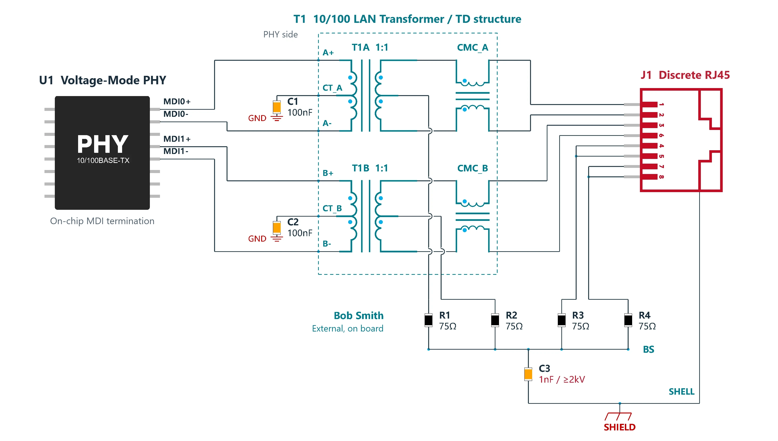
- Non-PoE
- On-chip MDI termination
- Each PHY-side CT to GND via 100nF
10/100BASE-TX Ethernet Schematic: Discrete RJ45 + External LAN Transformer (Voltage-Mode PHY)
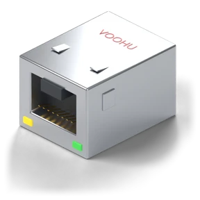
Non-PoE 10/100 Mbps Ethernet port reference circuit for voltage-mode PHYs with on-chip termination and CTs grounded through capacitors: a discrete RJ45 with an external TD-structure LAN transformer (isolation transformer + common-mode choke), each of the two CTs grounded through 100nF, and external 75Ω Bob Smith common-mode termination. VOOHU LAN transformers and RJ45s available.
D1.0Technical review draftView design →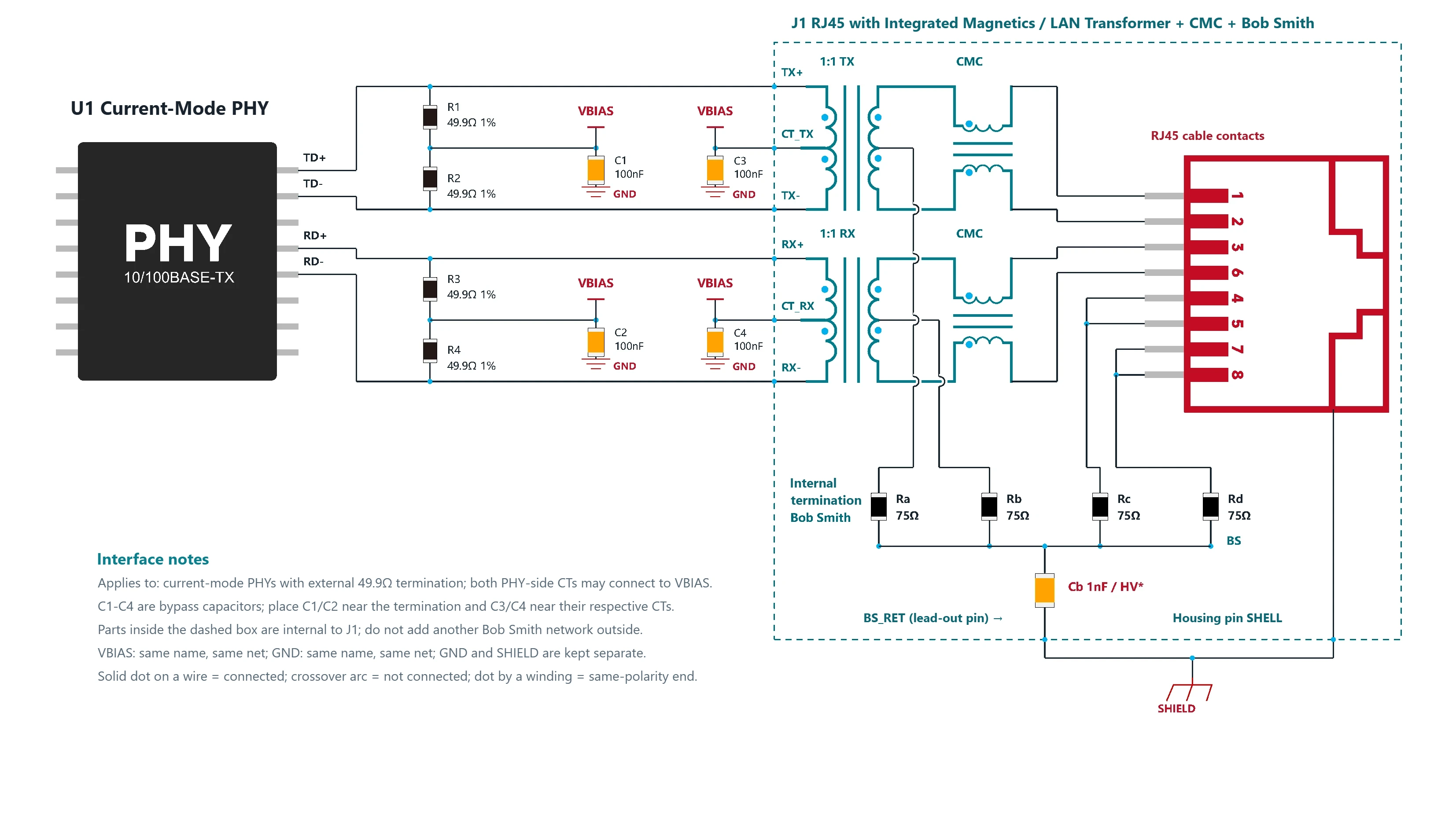
- Non-PoE
- External termination; both PHY-side CTs to bias supply
- RJ45 with integrated magnetics (ICM)
10/100BASE-TX RJ45 with Integrated Magnetics Schematic (Current-Mode PHY)
Non-PoE 10/100 Mbps Ethernet port reference circuit for current-mode PHYs with external termination: 49.9Ω pull-ups to VBIAS (typically 3.3V), and both CTs connected to VBIAS, each with its own 100nF bypass capacitor. The RJ45 with integrated magnetics contains the LAN transformer, the CMC (common-mode choke) and Bob Smith common-mode termination. VOOHU RJ45s with integrated magnetics available.
D2.6View design →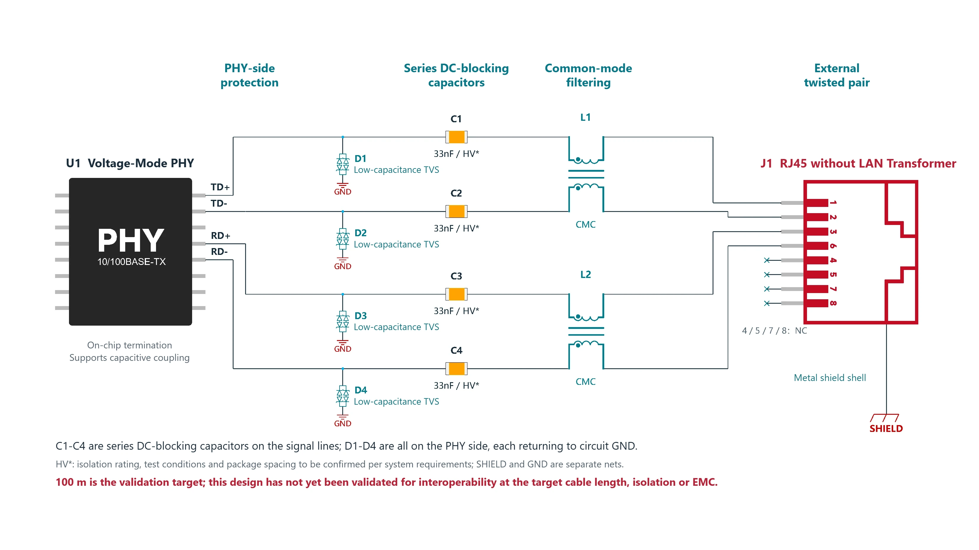
- Non-PoE
- External network cable
- On-chip termination, capacitive-coupling voltage-mode PHY
- 100 m is a target pending validation
Transformerless Ethernet Port: 10/100BASE-TX Capacitive Coupling with Chip LAN Common-Mode Choke (Voltage-Mode PHY)
Transformerless, capacitively coupled 10/100 Mbps Ethernet port for voltage-mode PHYs that support capacitive coupling and on-chip termination: a 33nF DC-blocking capacitor in series with each of TD± and RD±, low-capacitance TVS diodes on the PHY side, and a chip LAN common-mode choke to the RJ45. 100 m is pending validation. Uses VOOHU RJ45 and WHLC parts.
D1.1Dedicated validation editionView design →
Gigabit Ethernet port circuits (1000BASE-T)
1000BASE-T with four differential pairs, in two structures: discrete LAN transformer and RJ45 with integrated magnetics.
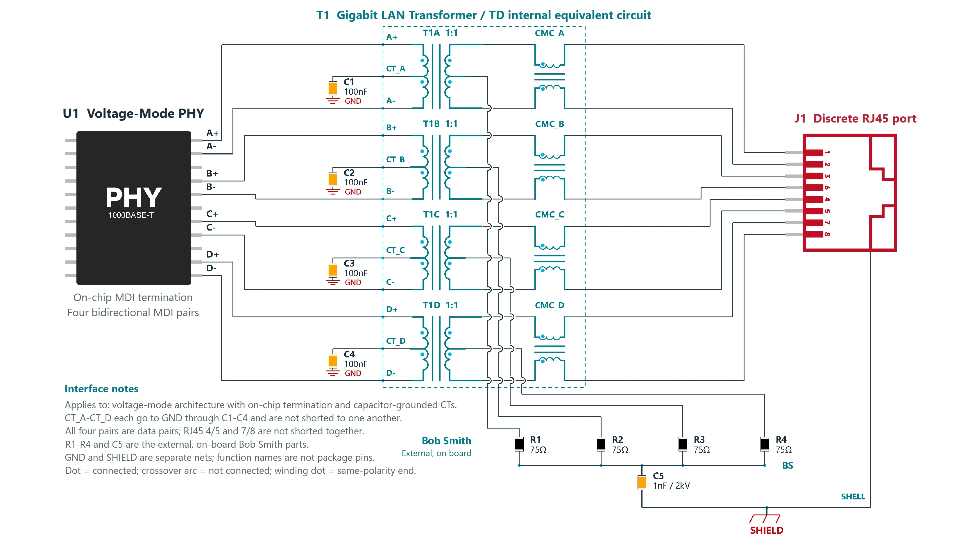
- Non-PoE
- Discrete RJ45 + external LAN transformer
- Voltage-mode architecture with on-chip termination
Gigabit Ethernet Transformer Schematic: Discrete RJ45 + External Magnetics (Voltage-Mode PHY)
Non-PoE Gigabit Ethernet port reference circuit for voltage-mode PHYs with on-chip termination and CTs grounded through capacitors: a discrete RJ45 with an external four-channel TD-structure LAN transformer (isolation transformer + common-mode choke), each of the four CTs grounded through 100nF, data on all four pairs, and external Bob Smith common-mode termination. VOOHU LAN transformers and RJ45s available.
D1.0View design →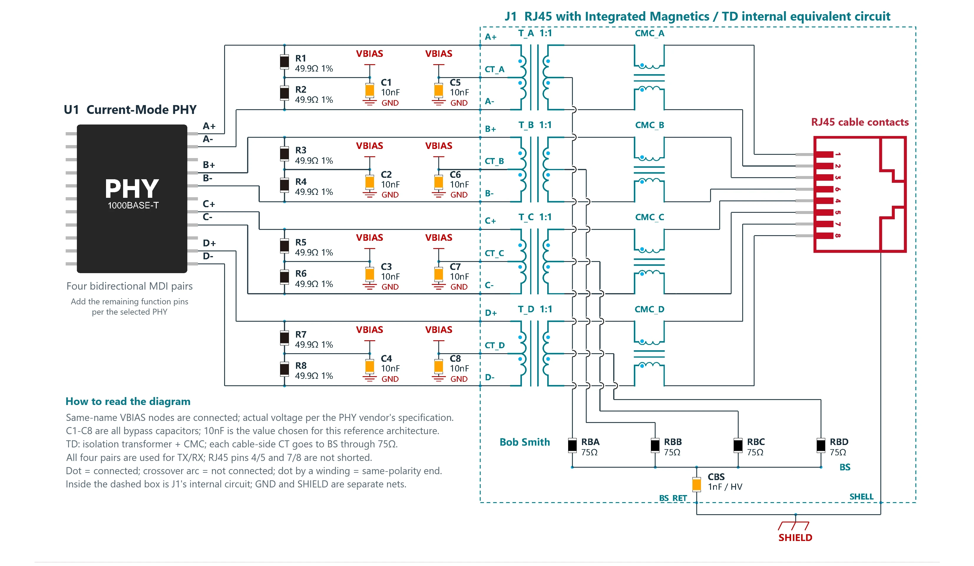
- Non-PoE
- TD magnetics structure
- Current-mode architecture with external termination
Gigabit RJ45 with Integrated Magnetics Schematic (Current-Mode PHY)
MDI reference circuit connecting a Gigabit current-mode PHY to an RJ45 with integrated magnetics: the external 49.9Ω terminations and all four CTs connect to VBIAS, with local bypassing. J1 contains the TD magnetics and Bob Smith termination. Uses a VOOHU RJ45 with integrated magnetics.
D1.4TD-structure editionView design →- FAE selection support
Your Gigabit design fits neither circuit?
Send your PHY model, port structure and PoE requirements to a VOOHU FAE to check the LAN transformer and RJ45 selection and the termination for your project.
What to send the FAE- PHY model
- Discrete RJ45 / RJ45 with integrated magnetics
- PoE requirements
10G Ethernet port circuits (10GBASE-T)
10GBASE-T copper interfaces with staged surge and ESD protection, in voltage-mode and current-mode PHY versions.
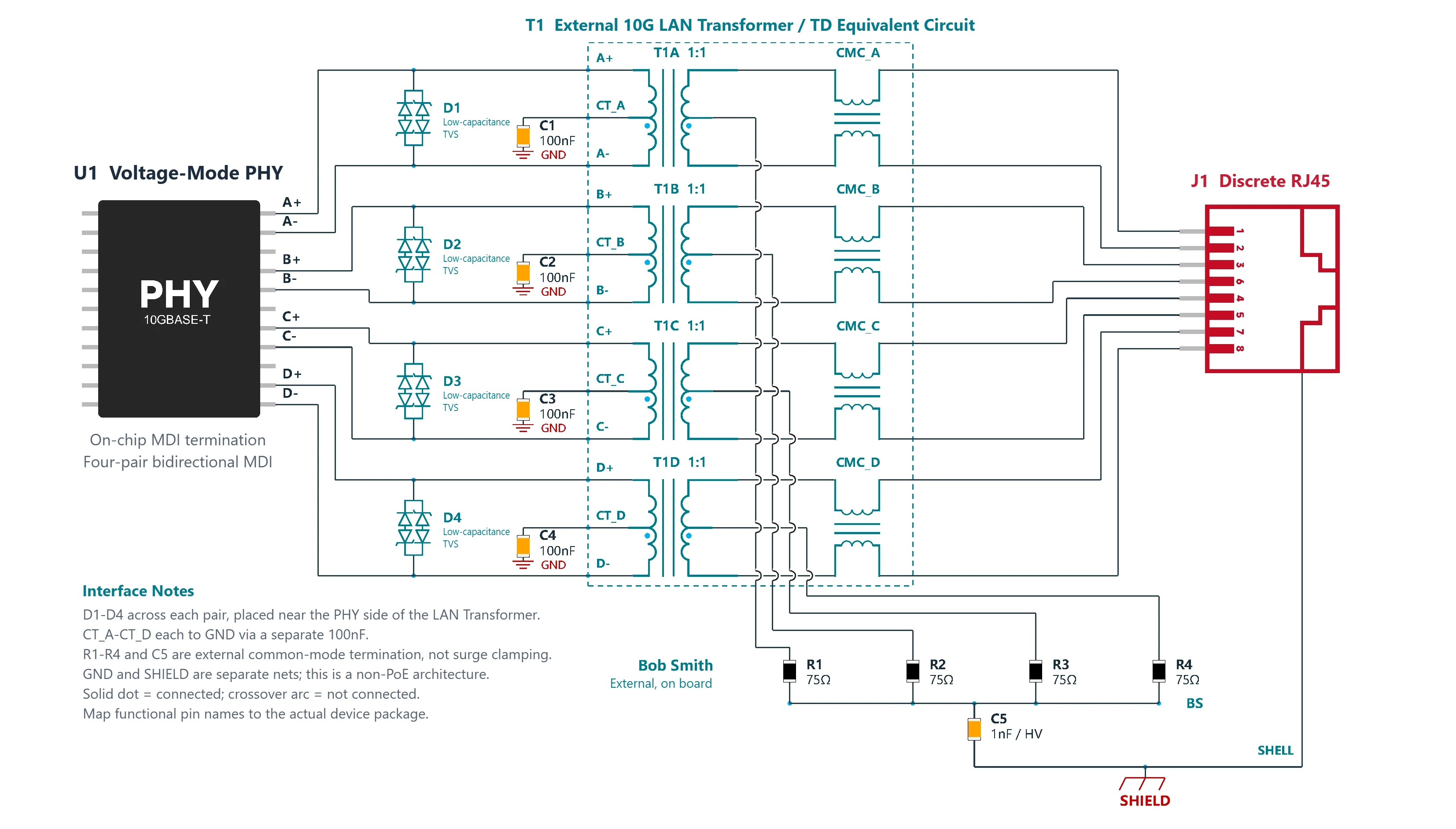
- Non-PoE
- Discrete RJ45 + external 10G LAN transformer
- TVS across differential pairs
10GBASE-T Ethernet Surge and ESD Protection Circuit (Voltage-Mode PHY)
Port protection circuit for a 10G voltage-mode PHY with on-chip termination: each CT grounded through 100nF, an external 10G TD-structure LAN transformer, low-capacitance TVS diodes across the pairs on the PHY side, and Bob Smith termination. Uses VOOHU RJ45, 10G LAN transformer and TVS parts.
D1.0View design →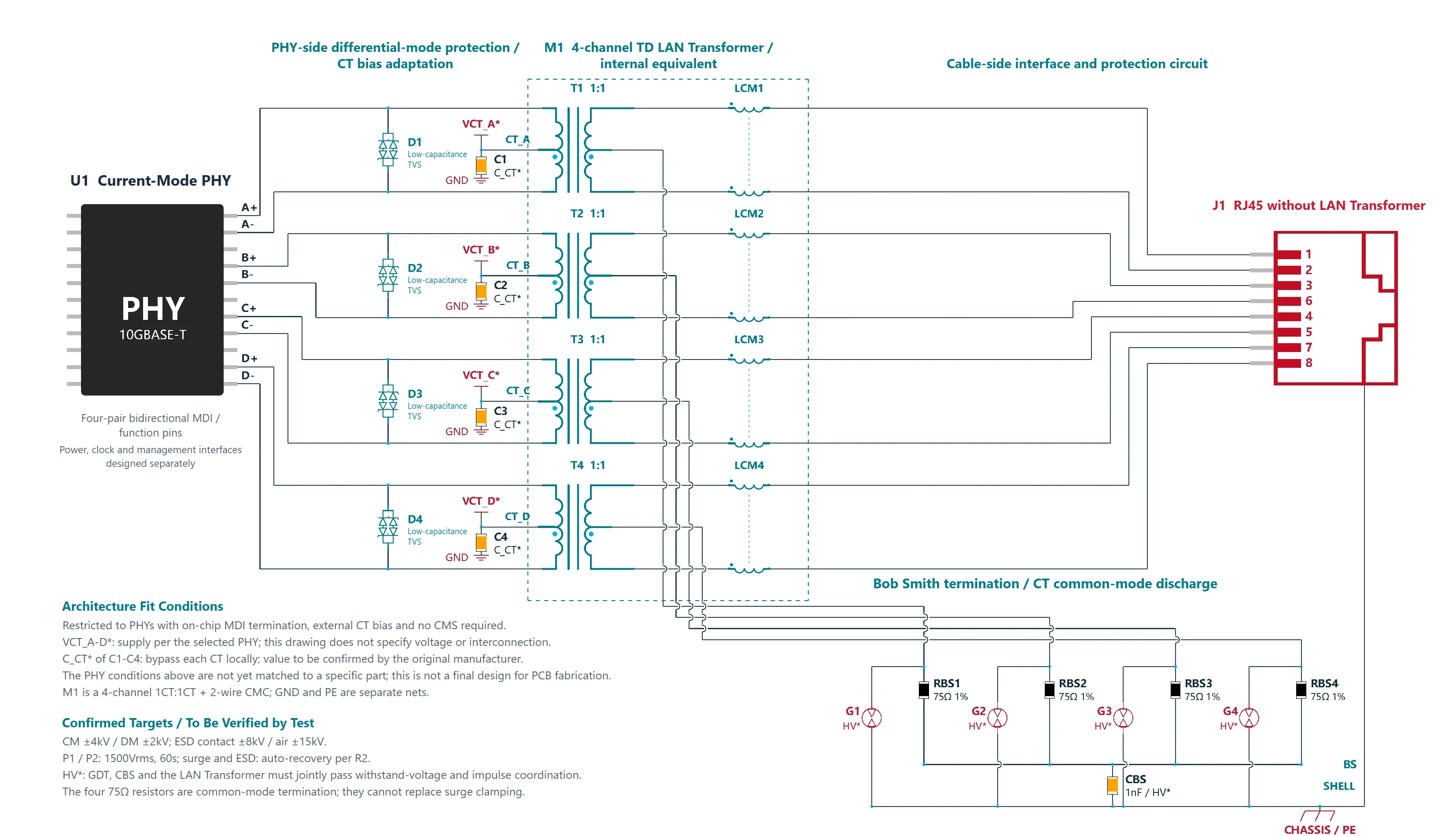
- Target: CM ±4kV / DM ±2kV
- ESD contact ±8kV / air ±15kV
- P1/P2 1500Vrms / 60s
- R2 automatic recovery
10GBASE-T Lightning Surge Protection for Current-Mode PHY: TVS + GDT Reference Design
Revised-architecture draft of a port protection circuit for a 10G current-mode PHY: the external CT bias is still to be confirmed, TVS diodes sit across the pairs on the PHY side, and the cable-side CTs connect to PE through a high-voltage GDT. Uses VOOHU RJ45, 10G LAN transformer, TVS and GDT parts.
D1.2Revised-architecture draftView design →- FAE selection support
Different protection targets for your 10G port?
Send your 10G PHY model and your surge and ESD protection targets to a VOOHU FAE to check the RJ45, 10G LAN transformer and protection parts against these two reference designs.
What to send the FAE- 10G PHY model
- Voltage-mode / current-mode
- Surge and ESD targets
Ethernet port surge and ESD protection circuits
10/100 Mbps and Gigabit Ethernet ports with an external TD-structure LAN transformer + staged protection devices.
- 10BASE-T / 100BASE-TX
- Non-PoE
- External pull-up termination / CT bias
- Reliable chassis ground / PE
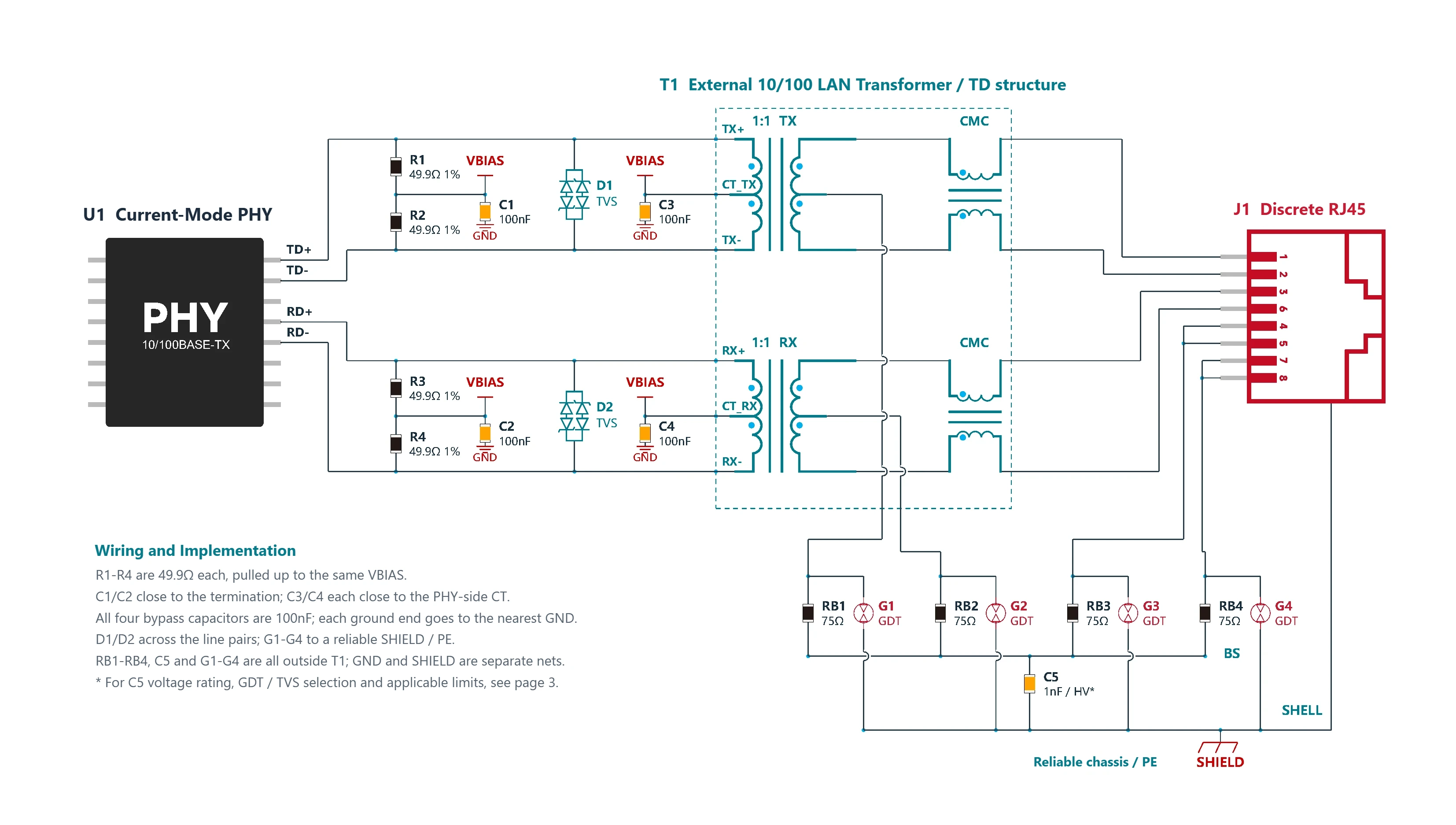
Ethernet Port Surge Protection Circuit: 10/100BASE-TX ESD and Surge Reference Design (Current-Mode PHY)
Non-PoE 10/100 Mbps Ethernet port protection circuit for current-mode PHYs: discrete RJ45 + external TD-structure LAN transformer, 49.9Ω pull-ups to VBIAS, staged protection with low-capacitance TVS diodes on the PHY side + a GDT on the cable side, and 75Ω + 1nF common-mode termination. Uses VOOHU LAN transformer, RJ45, TVS and GDT parts.
D1.0Technical review draftView design →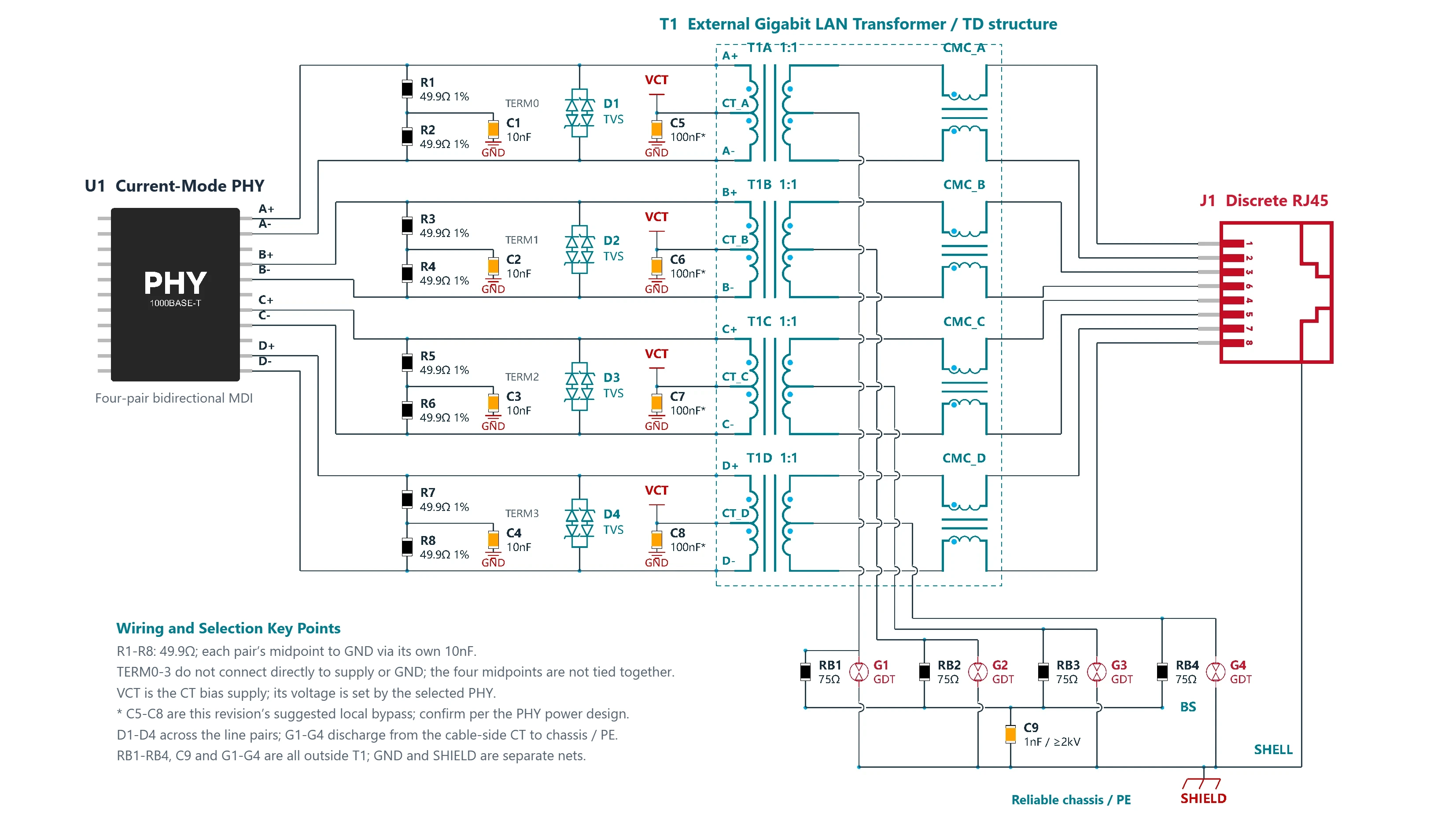
- 1000BASE-T
- Non-PoE
- External split termination / CT bias
- Reliable chassis ground / PE
Gigabit Ethernet Surge Protection Circuit: ESD and Surge Reference Design (Current-Mode PHY)
Non-PoE Gigabit Ethernet port protection circuit for current-mode PHYs: discrete RJ45 + external TD-structure LAN transformer, 2×49.9Ω split termination on each of the four pairs with the midpoint grounded through 10nF, and CTs connected to VCT; TVS diodes on the PHY side + GDT protection on the cable side, and 75Ω + 1nF common-mode termination. Uses VOOHU LAN transformers and other VOOHU parts.
D1.0Technical review draftView design →- FAE selection support
Different protection levels or grounding conditions?
Send your PHY model, data rate, surge and ESD protection targets, and whether a reliable chassis ground is available to a VOOHU FAE to check the TVS, GDT and LAN transformer selection for your project.
What to send the FAE- PHY model and data rate
- Surge and ESD targets
- Chassis ground / PE
What are the parts of an Ethernet port circuit, and what does each part do?
Signal path: PHY → RJ45
- PHY chip: Drives the MDI differential signals. A voltage-mode PHY terminates on-chip; a current-mode PHY needs external 49.9Ω termination and a bias on the center taps. This determines the peripheral circuit.
- Termination and center taps: With a current-mode PHY, each MDI line connects to VBIAS through 49.9Ω, and the center taps also connect to VBIAS. With a voltage-mode PHY, each center tap connects to ground through 100nF. Place every capacitor close to its pin.
- LAN transformer (TD): A 1:1 isolation transformer plus a cable-side common-mode choke. It provides isolation and suppresses common-mode noise. It can be a discrete external part or be integrated into the RJ45.
- Chip LAN common-mode choke: Used in transformerless designs together with DC-blocking capacitors, for common-mode filtering only. Isolation relies on the capacitors and spacing and must be confirmed by port isolation testing.
- RJ45 contacts: 10/100 Mbps uses two pairs, 1/2 and 3/6; 4/5 and 7/8 are unused. Gigabit and 10G transmit and receive on all four pairs, connected in order to 1/2, 3/6, 4/5 and 7/8.
Protection and grounding
- Bob Smith common-mode termination: The cable-side center taps (plus the unused pairs on 10/100 Mbps) each connect through 75Ω to one common point, which connects to chassis ground through a 1nF high-voltage capacitor. It is common-mode termination only and does not replace surge protection.
- TVS: Placed on the PHY side to limit the transients that reach the PHY. In designs with a LAN transformer, connect it across each pair; in capacitively coupled designs, connect it from each line to ground.
- GDT (gas discharge tube): Connected between the cable-side center taps and chassis ground (PE) to divert surge current. Select it together with the TVS and the magnetics.
- Chassis ground and circuit ground: The RJ45 metal shell connects to chassis ground (SHIELD). Circuit ground (GND) is a separate net; how the two connect is part of the system design.
The above is summarized from the reference designs on this page. For actual values, follow the vendor documentation for the selected PHY and the "Scope" section of each reference design.
How do voltage-mode and current-mode PHY peripheral circuits differ?
Voltage-mode PHY (on-chip termination)
- No external 49.9Ω termination resistors on the MDI lines
- PHY-side center taps (CT) connect to ground through capacitors
- CTs do not connect to a bias supply
Current-mode PHY (external termination)
- Each MDI line connects to the bias supply VBIAS through 49.9Ω
- PHY-side CTs also connect to VBIAS
- VBIAS is bypassed locally
The two circuits cannot be mixed. When selecting parts, follow the PHY vendor documentation. The "Scope" section of each reference design states which PHY architecture it applies to.
Discrete LAN transformer + RJ45 or RJ45 with integrated magnetics: how to choose?
Discrete design (external LAN transformer + discrete RJ45)
- Magnetics can be specified separately
- Easier to lay out protection devices
RJ45 with integrated magnetics (TD and Bob Smith common-mode termination inside the RJ45)
- Smaller board area
- Shorter traces
If you need surge protection, see the staged protection circuits in the "Ethernet port surge and ESD protection circuits" group.
Further reading
Need parts selected for your project?
Send your chip model, data rate, and power and protection requirements to a VOOHU FAE to check the peripheral parts against the reference designs.
Related solution areas
- Ethernet SolutionsSystem block diagrams and part selection
 Ethernet SwitchingMulti-port switching and PoE switches
 Single Pair Ethernet (SPE)T1L, T1S and power over data lines
 CAN / CAN FDTransceivers, signal isolation and bus protection
 RS-485 / RS-422Industrial serial buses and isolated interfaces
 High-Speed Signal InterconnectLVDS, SerDes and signal conditioning