Choosing a Chip LAN Transformer: Six Sizes Mapped to Data Rate, PoE Class and OCL | VOOHU
Choosing a Chip LAN Transformer: Six Sizes Mapped to Data Rate, PoE Class and OCL | VOOHU
The usual way to pick a chip LAN part is to open the selection table, sort by size and ask whether the smallest one will do. That order goes wrong at the first step, because the two smallest sizes — 2012 and 3216 — contain no transformer at all.
VOOHU currently offers 23 chip LAN order codes across six sizes, split into two entirely different classes. This article lays them out as a two-dimensional table of data rate against PoE class, and shows which size reaches which class, and why.
1. Two classes first: Cap+CMC and X'fmr+CMC
The selection table has a field called Classification with only two values. It is the most important division in the whole line.
| Class | Sizes | Prefix | What is inside |
|---|---|---|---|
| Cap+CMC | 2012, 3216 | WHLC- | Capacitors plus common mode choke. No transformer. |
| X'fmr+CMC | 3532A, 4532B, 4532E, 5335A | WHLT- | Transformer plus common mode choke. A real LAN magnetic. |
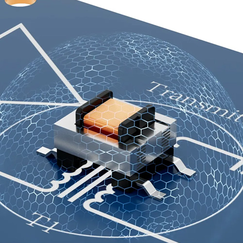
Cap+CMC parts serve transformerless (capacitively coupled) designs: the PHY is DC-blocked by capacitors and common mode noise is suppressed by the choke, with no magnetic isolation anywhere in the link. They save area and cost, and they give up the isolation and withstand voltage a transformer provides.
X'fmr+CMC is the conventional LAN transformer in a surface-mount package. If the design needs isolation, has to pass Hi-Pot, or carries PoE, the choice lies among those four sizes only.
So the first decision is not about size. It is one question: does this link need magnetic isolation? If yes, start at 3532A and strike 2012 and 3216 off the list entirely.
2. By data rate: all 23 order codes
2.1 100/1000 BASE-T
| Order code | Size | Class | OCL / impedance | PoE |
|---|---|---|---|---|
| WHLC-2012A-900T0 | 2012 | Cap+CMC | 90 Ω | Non-PoE |
| WHLC-2012A-181T0 | 2012 | Cap+CMC | 180 Ω | Non-PoE |
| WHLC-2012A-261T0 | 2012 | Cap+CMC | 260 Ω | Non-PoE |
| WHLC-2012A-361T1 | 2012 | Cap+CMC | 360 Ω | Non-PoE |
| WHLC-2012A-381T0 | 2012 | Cap+CMC | 380 Ω | Non-PoE |
| WHLC-2012A-801T0 | 2012 | Cap+CMC | 800 Ω | Non-PoE |
| WHLC-2012A-102T0 | 2012 | Cap+CMC | 1000 Ω | Non-PoE |
| WHLC-2012A-122T0 | 2012 | Cap+CMC | 1200 Ω | Non-PoE |
| WHLC-3216A-600M0 | 3216 | Cap+CMC | 60 µH | Non-PoE |
| WHLT-3532A-201MGN | 3532A | X'fmr+CMC | 200 µH @8 mA | Non-PoE |
| WHLT-4532B-201MGN | 4532B | X'fmr+CMC | 200 µH @8 mA | Non-PoE |
| WHLT-4532E-201MGN | 4532E | X'fmr+CMC | 200 µH @8 mA | Non-PoE |
| WHLT-4532B-201MGF | 4532B | X'fmr+CMC | 200 µH @8 mA | PoE af |
| WHLT-4532B-351MGF | 4532B | X'fmr+CMC | 350 µH @8 mA | PoE af |
| WHLT-4532B-121MGT | 4532B | X'fmr+CMC | 120 µH @10.8 mA | PoE at |
2.2 2.5G/5G BASE-T
| Order code | Size | Class | OCL | PoE |
|---|---|---|---|---|
| WHLC-3216A-550M0 | 3216 | Cap+CMC | 55 µH | Non-PoE |
| WHLT-3532A-151MQF | 3532A | X'fmr+CMC | 150 µH @8 mA | PoE af |
| WHLT-4532B-151MQT | 4532B | X'fmr+CMC | 150 µH @10.5 mA | PoE at |
| WHLT-4532B-181MQT | 4532B | X'fmr+CMC | 180 µH @10.5 mA | PoE at |
| WHLT-5335A-151MQB | 5335A | X'fmr+CMC | 150 µH @21 mA | PoE at |
2.3 10G BASE-T
| Order code | Size | Class | OCL | PoE |
|---|---|---|---|---|
| WHLT-3532A-121MMF | 3532A | X'fmr+CMC | 120 µH @10.5 mA | PoE af |
| WHLT-4532B-121MMT | 4532B | X'fmr+CMC | 120 µH @15 mA | PoE at |
| WHLT-5335A-121MMB | 5335A | X'fmr+CMC | 120 µH @15.75 mA | PoE bt |
The 10G row has only three parts, but it shows the pattern of the whole line most clearly. That is the next section.
3. Pattern one: a higher PoE class forces a larger size
Line up those three 10G parts:
| Order code | Size | OCL | DC bias | PoE |
|---|---|---|---|---|
| WHLT-3532A-121MMF | 3532A | 120 µH | @10.5 mA | af (15 W) |
| WHLT-4532B-121MMT | 4532B | 120 µH | @15 mA | at (30 W) |
| WHLT-5335A-121MMB | 5335A | 120 µH | @15.75 mA | bt (60/90 W) |
The inductance is identical at 120 µH. What changes is the DC bias condition in brackets: 10.5 mA, then 15 mA, then 15.75 mA — and the size climbs from 3532A to 4532B to 5335A in step with it.
The reason is direct. PoE current rides on the signal windings, and a higher class means more current per pair, which pushes the core further toward saturation. Holding 120 µH of open-circuit inductance under a larger bias requires more core cross-section, which means a larger package.
So identical nominal inductance does not make two parts interchangeable. Whether a chip LAN part can carry your PoE class is decided by the @xx mA condition after the OCL figure, not by the µH number in front of it.
Collected into a lookup:
| PoE class needed | Available sizes | Note |
|---|---|---|
| No PoE | 3532A / 4532B / 4532E | All three have a Non-PoE order code |
| PoE af (15 W) | 3532A / 4532B | 3532A tops out at af |
| PoE at (30 W) | 4532B / 5335A | 4532B is the workhorse for at |
| PoE bt (60/90 W) | 5335A only | One part: WHLT-5335A-121MMB |
The practical value: if the project commits to PoE++ (bt), the field narrows to a single part before anything else is decided, and the board has to reserve 5335A space. Settling that first saves a re-spin.
4. Pattern two: higher data rates need less OCL, not more
Compare the inductance ranges across the three rate bands:
| Rate band | OCL range | Order codes |
|---|---|---|
| 100/1000 BASE-T | 120 to 350 µH | 3532A-201MGN, four 4532B parts, 4532E-201MGN |
| 2.5G/5G BASE-T | 150 to 180 µH | 3532A-151MQF, two 4532B parts, 5335A-151MQB |
| 10G BASE-T | 120 µH throughout | One each from 3532A, 4532B and 5335A |
Gigabit spans 120 to 350 µH, the widest of the three. At 10G all three parts sit at 120 µH with no alternative. That runs against the intuition that a faster link must demand more from the magnetics.
Open-circuit inductance governs the low-frequency end: it sets insertion loss and the lower cut-off for the low-frequency content of the signal. The coding and spectral distribution of 10GBASE-T differ from gigabit and place less demand at the low end, while high-frequency insertion loss, return loss and mode conversion become the binding constraints. Those come from winding construction and parasitic control, not from piling on inductance.
The lesson for selection: do not carry gigabit intuition into 10G and reject 120 µH as "far smaller than the 350 µH gigabit part, so it cannot work." The two bands are judged differently. Pick from the order codes listed under the matching rate band.
5. 4532B and 4532E: same size, different paths
Both carry the 4532 size code and look nearly identical on a selection table, but their coverage is very different.
| Series | Codes | PoE coverage | Position |
|---|---|---|---|
| 4532B | 7 | Non-PoE / af / at | The PoE workhorse, also covers non-PoE |
| 4532E | 1 | Non-PoE only | Non-PoE dedicated |
More to the point: WHLT-4532B-201MGN and WHLT-4532E-201MGN match on all four published fields — rate, class, OCL (200 µH @8 mA) and PoE (Non-PoE).
So if the design carries no PoE today, either works. If the board might gain PoE later, land on the 4532B series: moving from 201MGN to 201MGF (af) or 121MGT (at) keeps the size and changes very little. With 4532E there is no PoE part to move to.
One caution: a shared size code does not guarantee identical pads and pinout. Before substituting across the two series, check the pin diagram and recommended land pattern in each datasheet rather than reusing the footprint library.
6. Picking among the eight 2012 impedance codes
For a transformerless design, the 2012 series offers eight common mode impedance values: 90, 180, 260, 360, 380, 800, 1000 and 1200 Ω.
Higher is not better. More common mode impedance suppresses common mode noise harder, but it also affects differential insertion loss and phase balance more. For gigabit and below, the usual approach starts mid-range, meets EMC first, then checks whether the eye has been damaged.
| Impedance | Bias | Note |
|---|---|---|
| 90 / 180 / 260 Ω | Signal integrity first | Least effect on differential loss, limited suppression |
| 360 / 380 Ω | Balanced | The usual starting point for gigabit |
| 800 / 1000 / 1200 Ω | Common mode noise first | For radiated failures; re-measure the eye |
Always verify on the board. The effect of a common mode choke on the differential signal cannot be read from the typical values alone — trace length, vias and the reference plane all change the real result.
7. A three-step method and a pre-prototype checklist
Compressed into an order you can follow:
Step one, decide on magnetic isolation. If the link needs isolation, must pass Hi-Pot, or carries PoE, rule out 2012 and 3216 and choose among the four X'fmr+CMC sizes. Only consider Cap+CMC when isolation is not required and board area is very tight.
Step two, fix the PoE class. bt means WHLT-5335A-121MMB and nothing else; at comes from 4532B or 5335A; af can be 3532A or 4532B; no PoE opens 3532A, 4532B and 4532E. This step sets the board area to reserve.
Step three, pick the order code from the table for your rate band, then open the datasheet and check the OCL bias condition, insertion loss and return loss against what your PHY requires.
| # | Check | Pass criteria |
|---|---|---|
| 1 | Class understood | Cap+CMC has no transformer; not for isolated links |
| 2 | PoE class matches the size | bt needs 5335A; at needs 4532B or above |
| 3 | OCL bias condition read | Go by the @xx mA figure, not the µH alone |
| 4 | Rate band matches | Pick from the codes listed under your rate band; do not cross bands |
| 5 | PHY-side requirements | Center tap and common mode termination per the PHY |
| 6 | Pads and pinout | Redraw the footprint from the datasheet when changing series |
| 7 | Reflow verification | Re-measure inductance and insertion loss after reflow |
| 8 | Hi-Pot and withstand | Run the withstand test where isolation is required |
| 9 | Impedance code measured | For 2012 designs, measure the eye and radiated emissions |
| 10 | Link tested at rate | Run BER and link stability, not just a negotiated LED |
8. Frequently asked questions
Q1. 2012 and 3216 are the smallest. Are they entry-level chip LAN transformers?
No. Their classification is Cap+CMC: capacitors and a common mode choke, with no transformer, for transformerless capacitively coupled designs. They provide no magnetic isolation. The smallest part with a transformer is 3532A.
Q2. Both are 120 µH. Can 3532A replace 5335A?
No. The inductance matches but the bias condition does not: WHLT-3532A-121MMF is @10.5 mA (PoE af) and WHLT-5335A-121MMB is @15.75 mA (PoE bt). Under PoE bt current the 3532A core is driven toward saturation and will not hold its inductance. The @xx mA figure is what decides this.
Q3. I need PoE++ (60 W / 90 W). What are the options?
Among current order codes only WHLT-5335A-121MMB is listed as PoE bt, in the 10G BASE-T band. If the link is not 10G but does need bt, send us the requirement and we will confirm what is available.
Q4. The Non-PoE parts in 4532B and 4532E have identical specs. Does the choice matter?
Either works today, but 4532B is the safer pick. 4532E has only that one Non-PoE code, so a later move to PoE leaves nothing in the same series; 4532B has af and at codes at the same size.
Q5. How do I read the 121, 201 and 351 codes?
On transformer parts (WHLT) they are inductance: two significant digits and a power of ten, so 121 = 12×10¹ = 120 µH and 351 = 350 µH. On capacitor parts (WHLC) they are common mode impedance: 102 = 10×10² = 1000 Ω, 122 = 1200 Ω. The same digits carry different units in the two families.
Q6. Can chip LAN replace a through-hole LAN transformer directly?
Functionally it maps across, but it is not a pin-compatible swap. Package, pinout, land pattern and reflow process all have to be redone, and inductance and insertion loss need re-measuring after reflow. Treat it as a design change, not a part change, and run the full verification.
Send us the PHY, the link rate, whether PoE is involved and at what class, and the board area available, and our engineering team will come back with matching order codes, a reference circuit and verification advice.
——— VOOHU Engineering Team
Technical support: fae.thorne@voohu.cn | Tel: +86 400-1048-018
Suzhou VOOHU Electronic Technology Co., Ltd. | www.voohuele.com