Chiplan and network transformer selection
The following is a more comprehensive technical comparison and design analysis of capacitive/inductive Chip LAN and integrated network transformers. The content is about 2 times deeper than the initial version, adding device internal structure analysis, more practical design challenge descriptions and industry application technology cases:
────────────────────────────────────────────────
#Part 1: Capacitive Chip LAN vs Integrated Network Transformer - A Systematic Analysis from Principle to Implementation
1. Device structure and physical principle
Capacitive Chip LAN:
- Architecture decomposition:
- Internally integrated high-voltage ceramic capacitors (withstand voltage 1-2kV) serve as an isolation layer, with differential-mode signal transmission networks connected on both sides.
- Comes with ESD protection diodes and micro common mode inductors to suppress spikes and EMI.
- Typical package: 0402/0603 chip package, full SMD design, no magnetic core.
- Signal path model:
- Presents low impedance to high frequencies, allowing signals to pass, but the DC path is blocked by the capacitor.
- Parasitic inductance (about 1-2nH) and distributed capacitance (0.5-1pF) directly affect the attenuation of signals above 10G.
Integrated network transformer:
- Architecture decomposition:
- Magnetic isolation core: Ferrite magnetic toroid or planar transformer structure, primary to secondary winding ratio 1:1 (or customized).
- Peripheral circuit: Built-in Chip RC network to balance common mode impedance, some modules integrate common mode choke (CMC).
- Package: DIP/SMD module (size 6x6mm to 15x15mm) with metal shielding.
- Magnetic coupling efficiency:
- The initial permeability (μi) and saturation flux density (Bs) of the core material determine the bandwidth and power handling capability.
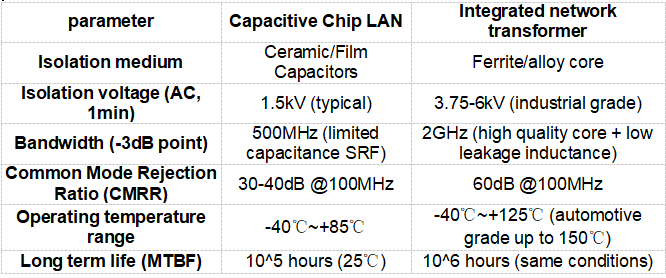
Key parameter comparison: capacitor type vs transformer type
────────────────────────────────────────────────
2. Deep challenges and solutions for hardware design
(1) Capacitive Chip LAN Design Risks
- Capacitor withstand voltage degradation:
- Repeated charging and discharging of high frequency and high voltage (such as PoE applications) causes aging of the capacitor dielectric and increased leakage current.
- Countermeasure: Choose high-stability ceramic capacitors such as X7R/X8R, and reserve 20% voltage margin.
- High frequency loss control:
- When the signal frequency is >1GHz, the capacitor self-resonant frequency (SRF) limits the effective bandwidth.
- Countermeasures: Shorten the trace length from PHY to capacitor (<5mm), disable vias and right-angle turns.
(2) Design risks of integrated network transformer
- Magnetic saturation problem:
- In high-power scenarios such as PoE++ (90W), large currents cause core saturation and skyrocketing losses.
- Countermeasures: Choose Sendust or nanocrystalline cores with high Bs values and increase the air gap (sacrificial inductance).
- High frequency radiation interference:
- Unshielded transformers become radiation sources in the GHz band, affecting RF circuits (such as Wi-Fi/BT modules).
- Countermeasures: Ground the module housing and arrange magnetic absorption materials (such as ferrite sheets) around it.
────────────────────────────────────────────────
3. Application scenario technology adaptation and typical cases
(1) Flexible application of capacitive chip LAN
- Fast charging and data transmission two-in-one (USB PD + Ethernet):
- In a USB Type-C docking station, use capacitive LAN to save space while supporting 100W power delivery.
- Design difficulty: PD protocol communication (CC line) and differential signal must be strictly isolated to prevent capacitive coupling noise.
- Industrial IoT low-power sensor network:
- In the RS-485 to Ethernet gateway, the capacitor isolation meets the basic 2kV withstand voltage, and there is no core hysteresis at -40℃ low temperature startup.
(2) High-end applications of integrated transformers
- 800G optical module SerDes interface isolation:
- Use ultra-wideband (supporting 56G PAM4) transformers and combine them with Linear Drivers to compensate for losses.
- SI verification: Use TDR (time domain reflectometer) to ensure impedance matching and PCB routing error within ±5%.
- Gigabit Ethernet backbone for electric vehicles:
- Mechanical reinforcement design of core and coil, epoxy resin potting to prevent breakage under vibration and temperature shock.
────────────────────────────────────────────────
#Part 2: Inductive Chip LAN vs Integrated Network Transformer - Breakthrough in High Frequency Performance and Reliability
1. Technological innovation of inductive chip LAN
(1) Fusion of magnetic integration and semiconductor technology
- 3D stacked inductor technology:
- Use TSV (through silicon via) to manufacture spiral inductors on silicon substrates, increasing the Q value by 30% and supporting 10GHz ultra-wideband.
- Typical manufacturers: TDK’s MLP series (Multi-Layer Pieced Inductor).
- Magnetic and electric composite isolation:
- Inductive isolation + capacitive coupling dual path, redundant design improves EMC level (such as meeting CISPR 32 Class B).
(2) Performance limits of inductive vs. traditional transformers

────────────────────────────────────────────────
2. High-frequency traps and cracking methods in hardware design
(1) Signal ringing suppression for inductive chip LAN
- Root cause:
- High-speed signal edges (<100ps) trigger LC resonance, and ringing causes the bit error rate (BER) to increase.
- Countermeasures:
- Add a 22Ω resistor (or an adjustable termination network) in series on the PHY side to match the driver impedance.
- PCB stack-up optimization: reference plane is complete (avoid cross-segmentation), and the spacing between signal layer and GND layer is <4mil.
(2) Multi-port crosstalk control of integrated transformer
- Root cause:
- Magnetic field coupling of multi-port transformers in switches deteriorates far-end crosstalk (FEXT).
- Countermeasures:
- The module spacing is ≥10mm, and a shielded ground plane is inserted between signal layers (Stripline structure).
- Serial ports are arranged in staggered layout, breaking the symmetrical coupling.
────────────────────────────────────────────────
3. Industry cutting-edge applications and technology trends
(1) SiP integration of inductive chip LAN
- Heterogeneous integration cases:
- Intel “Ethernet SiP”: PHY chip, inductor isolation, and TVS are integrated in a 5x5mm package with a rate of 2.5Gbps.
- Advantages: Reduce PCB area by 60% and increase yield to 99.8% (traditional modules 97%).
(2) Magneto-optical hybrid isolation technology
- Technical route:
- VCSEL (Vertical Cavity Surface Laser) and photodiode are embedded in the transformer magnetic circuit to achieve electric-magnetic-optical triple isolation.
- Withstands voltage exceeding 30kV and has been used in UHV substation monitoring systems.
(3) Research and development of quantum dot magnetic cores
- Innovation:
- Quantum dot-doped magnetic materials reduce high-frequency losses by 50%, supporting 1THz terahertz communication prototypes.
- Potential scenarios: 6G wireless backhaul network, high-precision radar interference isolation.
────────────────────────────────────────────────
4. Engineer Selection Decision Tree
Step 1: Prioritize requirements
- Isolation withstand voltage > 3kV? → Select a transformer
- Space cost sensitive? → Choose capacitive
- Rate > 10Gbps? → Choose transformer or advanced inductor
- Need automotive-grade certification? → Choose AEC-Q200 transformer
Step 2: Verify supply chain stability
- Capacitive Chip LAN: The supply cycle of Taiwanese manufacturers (Yageo/Walsin) is 8 weeks, and the yield of domestic alternatives (Fenghua) needs to be improved.
- Integrated transformer: Japan's TDK/Murata has a delivery time of 12 weeks, and the domestic alternative Magnetron Technology needs to evaluate long-term reliability.
Step 3: Preliminary research and test project
- Required items: Isolation withstand voltage test, TDR impedance verification, Thermal cycle (-55℃~+125℃ 1000 times)
- Optional items: HBM ESD test, salt spray corrosion test (maritime equipment), random vibration analysis (vehicle-mounted).
────────────────────────────────────────────────
#Summarize
Capacitive/inductive Chip LAN and integrated network transformer each have their own technical advantages:
- Miniaturization and cost: Capacitor/inductor Chip LAN dominates consumer electronics and lightweight IoT.
- Extreme reliability and performance: Integrated transformers are still the best choice for industrial, automotive and military applications.
- Future battlefield: 3D magnetic integration, quantum magnetic core, and magneto-optical hybrid isolation technology will reshape the industry landscape.
Design motto: "Isolation level and signal integrity are the first principles, and everything else is a trade-off."
Need a quote, samples or selection support?
Fill in the part number, quantity and lead time. Samples are available for evaluation, and selected parts are free of charge. Our FAE team will be glad to confirm the options for your project. Not sure about a parameter? Enter "Not sure". Need something non-standard? Choose Custom Design.
Before you order: samples, MOQ, lead time and import duties in our ordering guide →