An SFP cage PCB layout comes down to four checks. First, draw the cage holes and the 20-pin connector pads from the same cage drawing, because the drawing locates them relative to each other. Second, match the hole design to how the cage tails are terminated, press-fit or soldered, and to your assembly flow. Third, connect the cage pads and vias to chassis ground, not signal ground, and keep components and traces out of the area under the cage, except chassis ground; the connector area itself allows traces. Fourth, size the bezel cutout and panel position from the same drawing so the EMI springs touch the panel. VOOHU SFP and SFP28 cage drawings give each of these, and the product tables offer STEP 3D models for fit checks.

This checklist covers only how the cage sits on the board and in the panel. For what an SFP cage and connector are and how they pair, see what to know about SFP connectors; for the 20 signal pins, see the SFP connector pinout. Light pipes, heat sinks and plating corrosion have their own guides: SFP cage light pipes, SFP heat sink cages and SFP cage corrosion testing.
#What does an SFP cage footprint include?
An SFP cage footprint has two parts that share one set of datums: through-holes for the cage tails, and the surface pads and locating holes for the 20-pin host connector that sits inside the cage. The VOOHU drawing for the WH191R019D0S02 SFP 1x1 cage, for example, calls for 7 holes of 1.05 ±0.1 mm and 9 holes of 0.95 ±0.05 mm for the cage, plus 0.85 ±0.05 mm chassis ground holes, 2 locating holes of 1.55 ±0.05 mm for the connector, and 20 connector pads 0.50 ±0.03 mm wide in two rows at 0.8 mm pitch.
Take the cage holes and the connector pads from the same drawing and the same datum. The drawing notes that datums and basic dimensions are established by the customer, so place the datum where your mechanical team references the bezel, and keep it identical on the board and the panel drawings.
Values are copied from each part's VOOHU drawing; read the full drawing before releasing a footprint.
Do not mix numbers between drawings. The WHSFP30211W021 layout is drawn for a 3.0 mm board, while the other two are drawn for 1.57 mm, and hole counts differ from cage to cage. If your board thickness differs from the drawing, our FAE team can check the footprint for your stack-up.
#Should an SFP cage be press-fit or soldered?
Both are used, and the choice follows your assembly flow. A press-fit tail has a compliant section that is pressed into the hole and held by interference, with no solder, so the cage can go on after the surface-mount connector has been reflowed. A solder tail needs its own soldering step, and a solder-tail label alone does not mean the cage can go through reflow.
Where a drawing names the contact termination, it is stated outright. The drawing for the WHSFP15624D003 SFP+ 2x4 cage and connector assembly, for example, specifies "CONTACT NEEDLE EYE" with 2.54 µm minimum matte tin over 1.27 µm minimum nickel, a press-fit termination for its contacts.
The VOOHU SFP and SFP28 selectors list the installation type for each cage. Before you fix the hole design, tell our FAE team how the board will be assembled, and they will confirm the termination and hole details for the cage you choose.
#How should an SFP cage be grounded?
Connect the cage to chassis ground. The VOOHU drawings say so directly: "pads and vias are chassis ground" on the WH191R019D0S02 and WH391Y119D0S02, and an area "exposed to chassis ground" on the WHSFP30211W021. Chassis ground is the enclosure and front-panel potential, not the signal ground of the PHY or the SerDes. The cage is a shield: it should carry noise current to the enclosure rather than into the circuit ground under the high-speed lines. How chassis ground joins circuit ground elsewhere on the board is a system EMC decision outside the cage drawing.
Treat the area under the cage as the drawings mark it: no components and no traces there except chassis ground copper. The connector area is different: it is a component keep-out but traces are allowed, which is where the high-speed pairs enter the connector pads.
- Place the chassis ground pads and vias at every location the drawing shows.
- Keep signal-ground copper and other nets out of the hatched keep-out.
- Route the high-speed pairs into the connector pads through the area where traces are allowed.
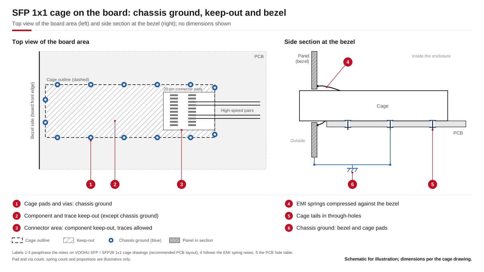
Board view and bezel section of an SFP 1x1 cage: chassis ground pads and vias, the keep-out under the cage, the connector area where traces are allowed, and EMI springs compressed against the panel. Schematic for illustration; dimensions per the cage drawing.
#What size should the SFP bezel cutout be?
Take the panel cutout from the same drawing as the footprint, because the cutout, the panel thickness and the distance from the panel to the cage front work together to put the EMI springs against the panel. The VOOHU drawings for the WH191R019D0S02 and WHSFP30211W021 give a recommended bezel design, and the WH391Y119D0S02 drawing gives the panel angle and thickness:
The WHSFP30211W021 is drawn with side EMI springs of phosphor bronze and copper alloy, and its drawing recommends a compression range of 0.2–0.8 mm. Check that range against your real panel position, including panel thickness and assembly tolerance: springs that do not reach the panel leave a gap in the shield.
For a panel that is not at a right angle to the board, use a cage drawn for it. The WH391Y119D0S02 is an 11° angled SFP28 cage with a cover, drawn for a panel at 79° to a 1.57 mm board, and its drawing shows the panel angle and thickness.
For several ports in a row, single 1x1 cages can sit side by side at no less than the minimum pitch on their drawing, 16.25 mm for both the WH191R019D0S02 and the WHSFP30211W021. A ganged 1xN cage, such as the 1x4 WHSFP01014W036 listed in the SFP selector, has its own footprint and cutout, so do not build it from repeated 1x1 footprints.
#Where can I get SFP cage dimensions and a 3D model?
Each VOOHU cage drawing gives the outline and the material. The WH191R019D0S02 is 14.00 ±0.10 mm wide and 45.55 mm maximum long, not counting the front springs, in nickel-plated copper alloy, rated −55 °C to +85 °C. The WHSFP30211W021 is 14.00 ±0.10 mm wide and 49.85 ±0.30 mm long, rated for operation from −40 °C to +105 °C.
The SFP and SFP28 product tables have a "3D model" button on most rows that downloads a STEP file, so your mechanical team can check the cage, the panel cutout and the heat sink or light pipe space in the enclosure model before samples arrive.
#Which VOOHU SFP cage fits your board?
- WH191R019D0S02: SFP 1x1 cage with a full set of drawings for footprint, chassis ground and bezel; listed as press-fit.
- WHSFP30211W021: SFP28 1x1 cage with side EMI springs and a stated 0.2–0.8 mm compression range; layout drawn for a 3.0 mm board; listed as press-fit.
- WH391Y119D0S02: SFP28 1x1 cage for an 11° angled panel, with a cover; listed as solder.
Compare every cage, including ganged versions, in the SFP connector and cage selector and the SFP28 selector. VOOHU also lists separate 20-pin SFP host connectors, such as the WH81-151-Y0002-1 and WHSFP30111F002; ask our FAE team to confirm the connector for the cage you choose.
#FAQ
Is an SFP cage connected to chassis ground or signal ground?
Chassis ground. VOOHU SFP and SFP28 cage drawings mark the cage pads and vias as chassis ground and keep other copper out of the area under the cage. The cage shields the port and should return noise to the enclosure, not to the signal ground of the PHY or SerDes.
Does a PCB-mounted SFP cage need a separate connector?
Yes, unless you buy a cage and connector assembly. The 1x1 cage is the metal housing; a 20-pin host connector is mounted on the board inside its footprint, and the cage drawing shows the connector pads and locating holes. Lay out both from the cage drawing so the module lines up with the connector.
Can I place SFP 1x1 cages side by side for a 1x4 port group?
Yes, at no less than the minimum port pitch on the cage drawing, which is 16.25 mm for the VOOHU WH191R019D0S02 and WHSFP30211W021. A ganged 1x4 cage is a different part with its own footprint and bezel cutout.
Why does a module not seat or get detected on my custom SFP board?
Check the mechanics first: the cage holes and connector pads must come from the same drawing and datum, the connector must sit flat on its pads, and the bezel cutout must not push the module off line. Then follow the electrical checks in SFP module not detected.
Get SFP cage samples and a footprint check
Send us your board thickness, assembly flow, port count and panel drawing through our sample and support form, and we will match a cage and connector set to your design. Our FAE team can suggest suitable parts and help check the design, from the footprint and chassis ground pads to the bezel cutout and EMI spring contact. Samples are available for evaluation, and selected parts are free of charge. Our FAE team will be glad to confirm the options for your project. VOOHU supplies RJ45 and SFP connectors, LAN and PoE transformers and common mode chokes from Suzhou, China, to more than 1,500 customers.
Need a quote, samples or selection support?
Part number WH191R019D0S02 is filled in for you. Add the quantity and lead time and submit. Our FAE team will be glad to confirm the options for your project.
Before you order: samples, MOQ, lead time and import duties in our ordering guide →