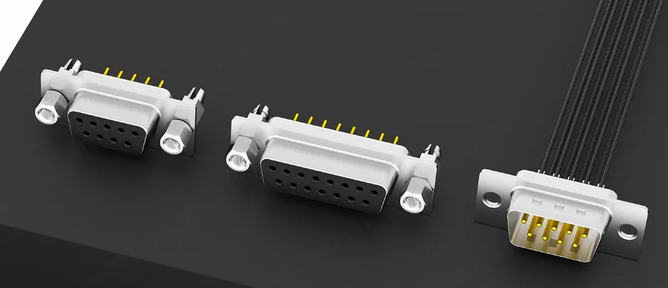
D-sub connector sizes are set by the shell, the trapezoidal (keystone) metal shell that also polarizes the mating. MIL-DTL-24308, the US detail specification for these connectors, numbers the shells: shells 1 to 5 carry 9, 15, 25, 37 and 50 standard-density contacts, or 15, 26, 44, 62 and 78 high-density contacts, and shell 6 carries 104 high-density contacts. Catalog names such as DE-9, DA-15 and DB-25 pair a shell letter with the contact count. To identify a connector, count the contacts and rows, then measure the mounting-hole spacing and shell width. On VOOHU drawings, a 9-position receptacle and a 15-position high-density receptacle share the same shell: 24.99 mm hole spacing and 30.81 mm width.

#What are the different types of D-sub connectors?
Shell size is only one of four choices, and a part number has to pin down all four:
- Density. Standard-density connectors use size 20 contacts; high-density connectors use smaller size 22D contacts, so the same shell holds more of them. MIL-DTL-24308 calls these Type I and Type II, and adds Type III for standard-density insulation displacement (IDC) contacts.
- Gender. Pin (male) or socket (female) contacts. The two mating halves always have opposite genders, so state which half sits on your board or panel.
- Termination. The specification covers crimp, solder, IDC and printed wiring board terminals. Board-mount parts come as straight (180°, vertical) or right-angle (90°) versions.
- Retention hardware. Board locks hold a PCB-mount part to the board; screw locks or threaded inserts hold the two connector halves together.
Checking only the contact count is not enough. A 15-position standard-density connector sits on shell 2, while a 15-position high-density connector sits on shell 1, so the two do not mate even though both have 15 contacts.
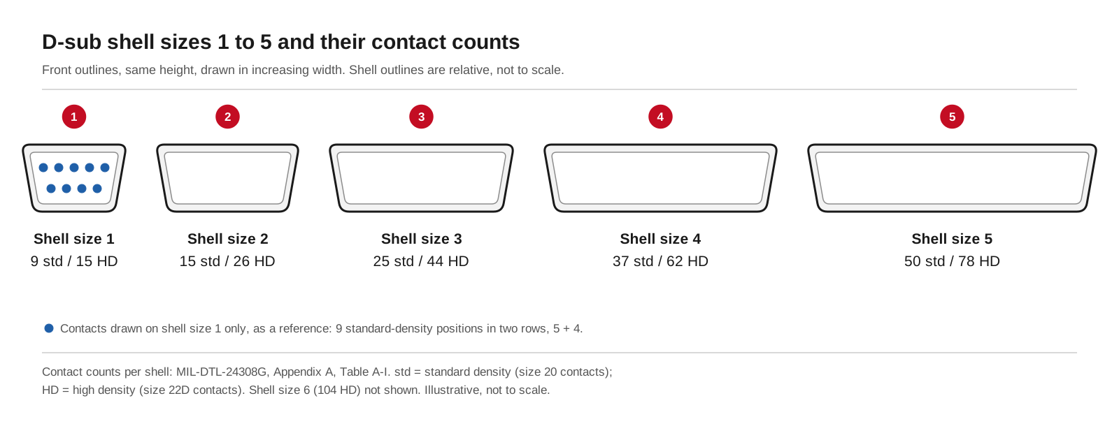
D-sub shell sizes 1 to 5 and the contact counts each shell carries in standard density (size 20) and high density (size 22D), per MIL-DTL-24308. Illustrative, not to scale.
#D-sub shell size chart
Contact counts are from MIL-DTL-24308G, Appendix A, Table A-I, published through the DLA ASSIST Quick Search. The specification itself uses numbered shell sizes; the letter names in the last column are a catalog naming convention, not part of MIL-DTL-24308. When you specify a connector, quote the shell size or the full part number rather than the letter alone. High-density parts are also named by contact count, and the 15-contact part on shell 1 is commonly called HD-15.
#DB9 vs DE9: what is the difference?
They name the same 9-position connector. In the lettered naming, the letter identifies the shell and B is the letter of the 25-position DB-25, so DE-9 is the precise name for a 9-position part on the smallest shell, while DB9 is a loose name in wide use. Neither name tells you the gender, the termination or whether the part is high density. In a design document or BOM, write something like "9-position D-sub, shell size 1, socket contacts, right-angle PCB mount", or quote the part number, and nobody downstream has to guess.
#How do you identify a D-sub connector size?
- 1.Count the contacts and the rows. A 9-position standard-density part has 5 + 4 contacts in two rows; a 15-position high-density part has three rows of five on the same shell.
- 2.Measure the mounting-hole spacing (centre to centre) and the shell width. These follow the shell, not the contact count, so they tell you the shell size directly. Compare them with the table below.
- 3.Decide the density. Fifteen contacts in three rows on the narrowest shell is high density; fifteen in two rows on the next shell up is standard density.
- 4.Read the rest from the drawing: gender, straight or right angle, board lock or screw lock, and the thread of the lock hardware.
B and C as given in the dimension tables of the VOOHU WHB050-series (standard density) and WHB0401-series (high density) drawings. Other dimensions, such as the shell front width, differ slightly between drawings, so read them from the drawing of the part you choose.
The matching rows are the practical proof that a DE-9 and an HD-15 share one shell: both have 24.99 mm hole spacing and a 30.81 mm shell. A panel laid out for shell size 1 is therefore the starting point for either density, but confirm the opening against the drawing of the exact part. The WHB050 part-number scheme also lists 15-, 25- and 37-position versions; ask our FAE team about the size you need.
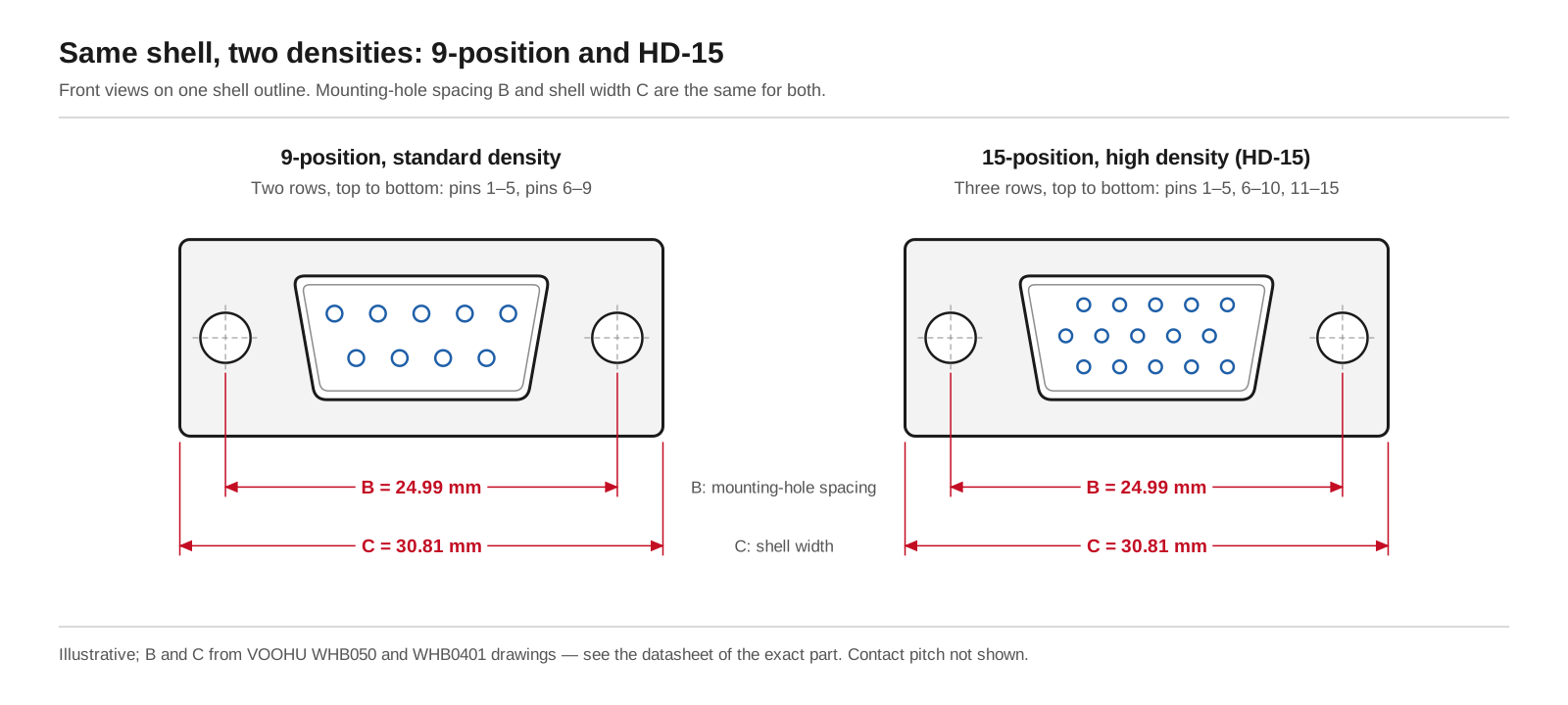
A 9-position standard-density layout (two rows) and a 15-position high-density layout (three rows) on the same shell: 24.99 mm mounting-hole spacing and 30.81 mm shell width on VOOHU drawings. Illustrative; see the datasheet of the exact part.
#D-sub connector cutout dimensions: where do you find them?
A panel cutout has two jobs: the opening has to clear the D-shaped front of the shell, and the two mounting holes have to line up with the connector's flange holes or threaded inserts. The hole spacing is the B dimension above. The opening itself depends on the shell front, the panel thickness and whether the connector mounts from the front or the rear of the panel, so take it from the drawing of the exact part, or from the MIL-DTL-24308 specification sheet for that connector style, rather than from a generic chart.
For the PCB side, the VOOHU drawings give the layout in full: contact holes of ø1.19 mm and mounting holes of ø3.20 mm on the WHB050XX6X1ADB2 and WHB04015611ADF4, a 2.77 mm contact pitch and 2.84 mm row spacing on the 9-position parts, and a 2.54 mm row spacing on the HD-15. For the panel opening, send us the part number and your panel thickness, and our FAE team will confirm the cutout for that part.
#What screw size do D-sub connectors use?
The VOOHU D-sub drawings that specify lock hardware give a #4-40 thread: the #4-40 UNC lock screws of the WHB050XX6X1XD02, the #4-40 hardware of the vertical WHB050XX8X1ADE5, and the 4-40 UNC nuts of the WHB04015611ADF4 HD-15. Whatever thread the drawing gives, the jack screws on the mating cable connector must use the same thread, so check both halves before you release the BOM. The WHB050XX6X1ADB2 is fixed to the PCB with riveted board locks; ask our FAE team which mating hardware suits your cable connector.
#Which VOOHU D-sub connector fits your board?
Where to start: for a general right-angle serial or control port, the WHB050XX6X1ADB2 is the reference 9-position part, and its drawing carries the full 9- to 37-position dimension table. If you want machined contacts and screw-lock hardware on the board side, look at the WHB050XX6X1XD02, rated 5 A. For a board that stands perpendicular to the panel, the WHB050XX8X1ADE5 is the 180° straight version. If you need 15 signals on the 9-position shell footprint, the WHB04015611ADF4 is the HD-15. Compare them in the D-sub connector selector, or filter for 5 A parts. For shielding, grounding and ESD at a D-sub port, see our industrial D-sub interface design guide.
#FAQ
Is RS232 the same as DB9?
No. RS-232 is an electrical interface standard for serial signals, while DB9, more precisely DE-9, is a 9-position D-sub connector. Many serial ports carry RS-232 on a 9-position D-sub, but the same connector is used for other interfaces, and RS-232 is also found on other connectors. Check the pin assignment of your interface, not the connector name.
Should I choose a crimp-type or a PCB-mount D-sub?
It depends on which half you are designing. Crimp D-subs take removable contacts crimped onto wire and suit cable assemblies; solder-cup versions suit hand-wired cables; PCB-mount receptacles solder into the board. MIL-DTL-24308 covers crimp, solder, IDC and printed wiring board styles. The VOOHU D-sub connectors in our selector are PCB-mount receptacles, so the crimp or solder-cup part is the mating cable connector.
What pin size do D-sub connectors use?
MIL-DTL-24308 uses size 20 contacts for standard density and size 22D contacts for high density. That is why a high-density connector fits more contacts into the same shell, and why standard and high-density contacts are not interchangeable. On the PCB, use the hole size and pitch from the drawing of the exact part.
Get D-sub samples checked against your panel and PCB
Send the contact count, density, gender, mounting direction and panel thickness through our sample request form. Our FAE team can suggest a VOOHU D-sub that fits and check the PCB layout, mounting holes and panel cutout against the drawing. Samples are available for evaluation, and selected parts are free of charge. Our FAE team will be glad to confirm the options for your project. VOOHU supplies RJ45 and SFP connectors, LAN and PoE transformers and common mode chokes from Suzhou, China, to more than 1,500 customers.
Need a quote, samples or selection support?
Part number WHB050XX6X1ADB2 is filled in for you. Add the quantity and lead time and submit. Our FAE team will be glad to confirm the options for your project.
Before you order: samples, MOQ, lead time and import duties in our ordering guide →