An ideal audio transformer changes impedance by the square of its turns ratio: Zp / Zs = (Np / Ns)². To find the turns ratio for a match, take the square root of the impedance ratio, so matching 600 Ω to 15 kΩ takes about 1:5. Real parts add winding resistance and need enough primary inductance at your lowest frequency, so treat the formula as the starting point, not the answer. On 1:1 transformers for 600 Ω lines, an impedance pair such as 600 Ω : 290 Ω describes the termination the windings are designed for, not a ratio to feed into the formula. VOOHU audio transformer datasheets state the turns ratio on its own line, for example 6.0:1 on the WHTT4103 (measured at 10 kHz and 1.0 Vrms) and 1:1 on the WHTT4204 with its 600 Ω line side, so you can run the calculation from the datasheet.
#What is the impedance matching transformer formula?
For an ideal transformer with turns ratio n = Np / Ns, the secondary voltage is the primary voltage divided by n and the secondary current is the primary current multiplied by n. A load ZL on the secondary therefore appears at the primary as Zin = n² × ZL. Two consequences catch people out: a modest 2:1 ratio already gives a 4:1 impedance change, and a 1:1 transformer passes the impedance through unchanged. A 1:1 part isolates and balances a line; it does not transform the impedance.
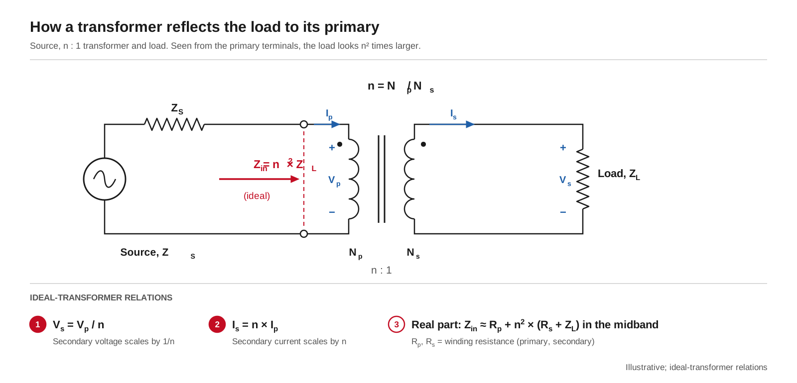
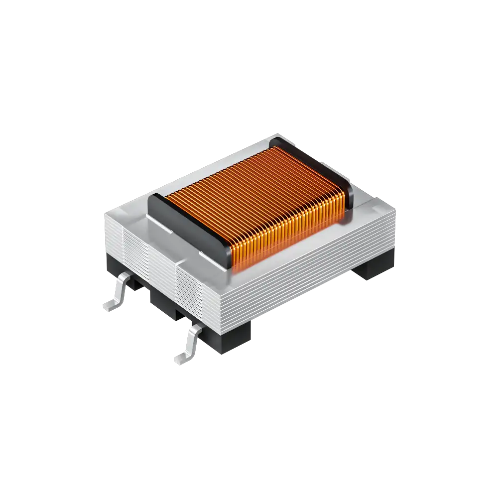
How an audio transformer reflects impedance: with turns ratio n, the load ZL appears at the primary as n² × ZL in the ideal case; winding resistance adds to it in a real part. Illustrative.
#How do you calculate the turns ratio from source and load impedance?
An audio transformer impedance calculator runs the same five steps you can do by hand:
- 1.Decide what "matched" means for your interface. For maximum power transfer, the reflected load equals the source impedance. Many line and microphone inputs are designed for bridging instead, where the load is much higher than the source so the source voltage arrives with little loss. Check which one your system specification asks for before you calculate anything.
- 2.Calculate n = √(Zp / Zs), using the impedance you want to see at the primary and the actual load on the secondary.
- 3.Add the winding resistances. Referred to the primary, the midband input is about Rp + n² × (Rs + ZL), where Rp and Rs are the DC winding resistances on the datasheet.
- 4.Check the low end. The reactance of the primary inductance, 2πfL, should stay well above the reflected impedance at the lowest frequency you need, or the response rolls off there.
- 5.Read the test conditions. Turns ratio and inductance are measured at a stated frequency and level; compare like with like.
Worked example with a VOOHU part: the WHTT4103 datasheet specifies a 6.0:1 turns ratio (±1 %, pins 1-2 to 4-3, measured at 10 kHz and 1.0 Vrms), winding resistances of 62 Ω (1-2) and 3.2 Ω (4-3), and at least 330 mH primary inductance at 1 kHz. For an ideal transformer, 6:1 corresponds to a 36:1 impedance ratio. Suppose you put a 50 Ω resistive load across pins 4-3. The ideal reflected impedance is 36 × 50 = 1,800 Ω; adding the winding resistances gives about 62 + 36 × (3.2 + 50) ≈ 1,980 Ω at the primary. That is an ideal-model estimate, not a datasheet impedance rating. The real input impedance also depends on inductance and frequency, so send our FAE team your source impedance, load and frequency band, and they can check the result for your circuit.
#600 Ω line transformer ratings: what does 600 Ω : 290 Ω mean?
"600 Ω" in audio is the nominal impedance of telephone-type (POTS) and similar balanced line interfaces, and transformers for those lines often carry an impedance pair on the datasheet. On 1:1 parts, that pair is the termination the windings are designed and tested with, not a ratio you can put into n². The WHTT4204 is a clear case: its drawing labels pins 1-2 "600 Ω line" and pins 4-3 "290 Ω device", yet the turns ratio is 1:1 ±1 %. Its insertion loss is measured with 290 Ω on pins 3-4 and its return loss against a 600 Ω reference, because 290 Ω plus the two winding resistances (141 Ω and 171 Ω) makes the line side look like about 600 Ω. The WHTT6033, rated 600 Ω : 430 Ω with a 1:1 ±1 % ratio, works the same way. When a datasheet gives both a turns ratio and an impedance pair, use the turns ratio for the formula and the impedance pair as the termination to apply. Our guide to 600 Ω audio transformer secondary termination works through the calculation and what goes wrong with the wrong resistor.
#Impedance matching transformer for a microphone: what changes?
The formula is the same, but at a microphone input the aim is usually voltage gain and a source impedance that suits the preamplifier, not a power match. Suppose a low-impedance microphone with a 150 Ω source drives a preamplifier through a 1:4 step-up. The signal voltage rises four times, and the preamplifier sees the source as 4² × 150 Ω = 2,400 Ω. Looking the other way, the microphone sees the preamplifier input divided by 16, so a step-up also loads the microphone more heavily. Choose the ratio as a balance between those two effects, then check the frequency response at that ratio. This section explains the principle only; for a part recommendation, send your microphone and preamplifier data to our FAE team.
#Impedance matching with audio transformer windings: series, parallel and taps
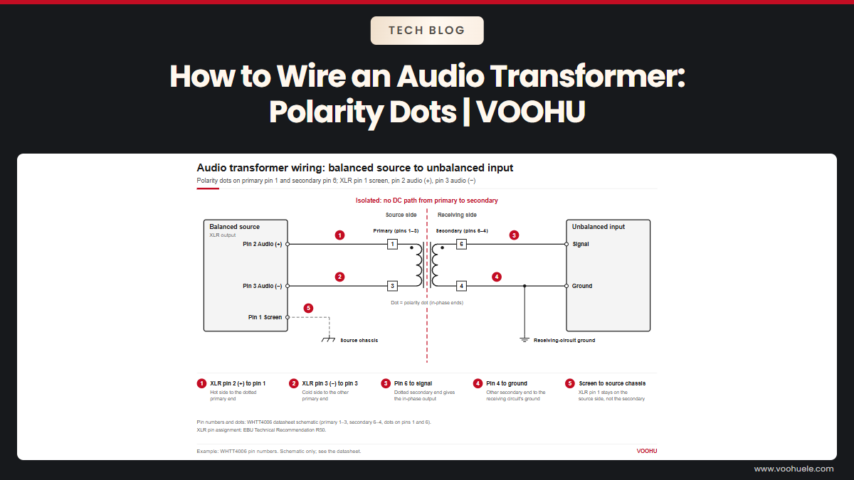
Connecting two identical windings in series doubles the turns on that side, so the impedance there rises four times. Connecting them in parallel keeps the turns the same and halves the winding resistance, but only if the windings are identical and phased correctly. A tapped winding gives a second, lower ratio from part of the winding. The WHTT5000, for example, has a 2:1 secondary-to-primary turns ratio (±2 %, pins 6-4 to 1-3, measured at 20 kHz and 1 V) and a tap on the secondary at pin 5. Across the full secondary, that is an ideal 1:4 impedance step-up from the primary; ask our FAE team for the ratio at the tap. Before you join windings, check the polarity dots: see how to wire an audio transformer.
#Which VOOHU audio matching transformer fits your interface?
All values are from the VOOHU datasheets with the test conditions shown. Where to start: for a 600 Ω line port that needs isolation without changing the impedance, the WHTT4204, terminated as its datasheet specifies. For isolating a 10 kΩ circuit, the WHTT6016. For a step-down that transforms impedance, the WHTT4103; for a 1:2 voltage step-up with a tapped secondary, the WHTT5000. Compare all parts in the audio transformer selector or the 4-pin audio transformers, and see audio isolation transformer selection for 600 Ω and 20 kΩ loop checks.
#FAQ
How do you measure audio transformer impedance?
Load the secondary with the resistor your design or the datasheet specifies, drive the primary from a signal generator through a known series resistor at a midband frequency, and calculate the input impedance from the voltages across the resistor and the primary. Measure the turns ratio separately as the open-circuit voltage ratio, at the frequency and level the datasheet uses; for the WHTT4103 that is 10 kHz and 1.0 Vrms.
Is the impedance ratio of a matching transformer always the turns ratio squared?
For an ideal transformer with a resistive load, yes: impedance ratio = (turns ratio)². In a real part, winding resistance and inductance shift the result, especially at the band edges. Also, an impedance pair printed on a line transformer datasheet can be a termination condition rather than a ratio: the WHTT4204 is rated 600 Ω : 290 Ω with a 1:1 turns ratio. Read the turns ratio line first.
How do you impedance-match an audio amplifier to a transformer?
Start from what the amplifier is specified to drive. A line driver usually has a low output impedance and a minimum load rating, so reflect the transformer load through n², add the winding resistances, and confirm the result stays above that minimum across your band. If the line needs a defined source impedance, such as 600 Ω, the series resistance is added on purpose, not left to the transformer.
Ask our FAE team to check the ratio for your source and load
Send your source impedance, load impedance, signal level, lowest and highest frequency and isolation voltage through our sample request form. Our FAE team can suggest a VOOHU audio transformer with a suitable turns ratio and check the reflected impedance, winding resistance and inductance against your circuit. Samples are available for evaluation, and selected parts are free of charge. Our FAE team will be glad to confirm the options for your project. VOOHU supplies RJ45 and SFP connectors, LAN and PoE transformers and common mode chokes from Suzhou, China, to more than 1,500 customers.
Need a quote, samples or selection support?
Part number WHTT4204 is filled in for you. Add the quantity and lead time and submit. Our FAE team will be glad to confirm the options for your project.
Before you order: samples, MOQ, lead time and import duties in our ordering guide →