Compiled from both manufacturers' published datasheets. Verify with samples and the PCB footprint before production.
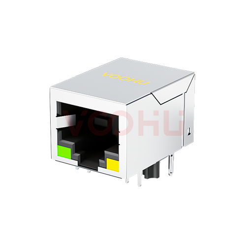
If your board carries the HanRun HY911130A, the VOOHU SYT-320DNL is a functional alternative — verify with samples in your design. Both are single-port, tab-down, through-hole RJ45 jacks with integrated magnetics (MagJack) for gigabit Ethernet, each with 10 signal pins and 4 LED pins. On the two drawings, the pin functions, LED colors and polarity, signal and LED hole positions, and the 350 µH minimum OCL read the same. The first thing to settle is on paper rather than on the board: the two datasheets test common-mode rejection, crosstalk and return loss against different limit lines and frequency bands, so an inspection sheet written for the HY911130A cannot be reused as it stands. Two hole sizes also differ, and both are covered below.
#What the HY911130A and SYT-320DNL datasheets each state
The HanRun column is taken from the HY911130A datasheet, revision A, a two-page document: electrical data and schematic on page 1, mechanical drawing, recommended PCB layout and LED data on page 2. The VOOHU column is taken from the SYT-320DNL datasheet, revision A0, which runs to three pages: mechanical drawing, recommended layout and materials on page 1, schematic, electrical table and LED data on page 2, and a wave-solder profile on page 3. Lengths are in millimetres. Where a datasheet gives no figure, the cell says "not stated"; no gap has been filled from another part in either family.
#CMR, crosstalk and return loss: same tests, different limit lines
This is where a quality engineer will spend most of the time. Both datasheets list insertion loss, return loss, common-mode rejection (CMR) and crosstalk, but they draw the limits in different places. HanRun gives CMR as −40 dB minimum from 1 to 60 MHz and −35 dB from 60 to 100 MHz; VOOHU uses a single line, −30 dB minimum from 1 to 100 MHz. For crosstalk, HanRun lists −35, −26 and −24 dB over 1–10, 15–60 and 60–100 MHz, and VOOHU lists −40, −35 and −30 dB over 1–30, 30–60 and 60–100 MHz. Return loss is cut into different bands altogether. HanRun starts at 0.3 MHz and runs to 100 MHz, with no figure for 30–40 or 60–80 MHz; VOOHU starts at 1 MHz and stops at 80 MHz. Even insertion loss is split differently: one line from 1 to 100 MHz on the VOOHU sheet, two segments with a break at 60 MHz on the HanRun sheet.
None of this ranks one part above the other in your product. Each figure is a limit the supplier tests its own part against, at its own frequency points, and the two sets were not written to a common template. What it does change is paperwork. If your incoming inspection or approval sheet was copied from the HY911130A datasheet, testing SYT-320DNL lots against it can produce disagreements that say nothing about the parts, because a band your sheet checks may be split differently, or not listed, on the VOOHU datasheet. Rewrite the electrical section of the sheet from the SYT-320DNL datasheet, item by item and band by band, and keep the HanRun version for HanRun lots only. If one of your system requirements was traced back to a specific HanRun figure, such as return loss between 80 and 100 MHz, cover it with board-level link and EMC testing on samples, and ask our FAE team what data is available for that band.
#Isolation and LED lines: what changes in the safety file and the schematic
The isolation line is worded differently, not just numbered differently. HanRun prints 1500 Vrms from the UTP side to the chip side, adds on page 2 that this is the minimum "per IEEE802.3 requirement", and gives no test time or trip current. VOOHU specifies the hi-pot test as 1500 V AC and 2250 V DC for 6 s at 1 mA, primary to secondary. If your safety report or critical-component list names the jack together with its isolation rating, that entry has to follow the approved part's own wording, so confirm with our FAE team which SYT-320DNL document and revision the entry should cite when you start the update. If your end product runs its own hi-pot step, our article on why Ethernet ports fail hi-pot tests walks through where the barrier sits.
For the hardware engineer, the LED line is the one that touches the schematic. Both parts put green on the left and yellow on the right, both drive green from pin 11 to 12 and yellow from 14 to 13, and both list 20 mA. The forward-voltage window is written differently: HanRun gives one range, 1.8–2.8 V, for both colors, while VOOHU gives 1.85–2.45 V for green and 1.7–2.2 V for yellow. If your series resistors were sized from a forward-voltage figure, recompute the current at both ends of each VOOHU range for your LED supply rail. Then look at a powered sample, particularly where green and yellow have to appear balanced on a front panel.
#Which holes need attention on a board laid out for the HY911130A?
Signal-pin holes, LED holes and the 11.43 mm peg spacing read the same on both recommended layouts. Two figures do not. The shield-tab holes are Ø1.63 mm on both, but HanRun spaces them 15.49 mm apart and VOOHU 15.75 mm. On a board drilled to the HanRun layout, each VOOHU tab therefore sits 0.13 mm outboard of its hole centre, half of the 0.26 mm difference. Whether the tabs still go in cleanly depends on the tab width and your finished-hole tolerance, and neither drawing settles that, so treat it as a trial-insertion item on boards you already have. The peg holes are Ø3.25 mm on the HanRun layout and Ø3.20 mm on the VOOHU layout. A board drilled for HanRun gives the VOOHU pegs slightly more clearance; if you intend to keep both parts approved on one layout, check the fit in both directions and agree the final hole sizes with our FAE team.
For the EMS side, the VOOHU datasheet supplies something the HanRun datasheet leaves out: a wave-solder profile on page 3, peaking at 260 ± 5 °C with no more than 5 s at peak, for Sn96.5/Ag3/Cu0.5 solder. Compare your current profile with it before the first lot. The same page notes that the plastic locating pegs under the board will melt slightly during wave soldering without affecting function, so brief your visual inspectors and a softened peg tip will not be logged as a defect. The outlines are within a few tenths of a millimetre of each other (21.30 × 16.04 × 13.50 mm against 21.10 × 16.00 × 13.45 mm), which only matters where the front-panel opening is tight.
#A change-over checklist for HY911130A boards
Quality and incoming inspection
- 1.Rebuild the electrical inspection items from the SYT-320DNL datasheet: insertion loss over 1–100 MHz, return loss in its four bands up to 80 MHz, CMR over 1–100 MHz and crosstalk in its three bands.
- 2.Replace the isolation entry in the approval sheet and the safety component list with 1500 V AC / 2250 V DC, 6 s, 1 mA, primary to secondary.
- 3.Before the first lot arrives, confirm with our FAE team which SYT-320DNL document and revision the approval sheet should cite.
Hardware design
- 1.Recalculate LED current at 1.85–2.45 V (green) and 1.7–2.2 V (yellow) and check brightness on a powered sample.
- 2.List any system requirement traced to a band only the HanRun sheet covers, and plan board-level tests for it.
Layout and EMS
- 1.Trial-insert samples into a board drilled for the HY911130A, watching the shield tabs (15.49 vs 15.75 mm spacing) and the pegs (Ø3.25 vs Ø3.20 mm).
- 2.Check your wave-solder profile against the page-3 profile and tell inspectors about the peg note.
- 3.If both parts stay approved on one layout, settle the shield-tab and peg hole sizes with our FAE team.
Purchasing
- 1.Enter the SYT-320DNL as a functional alternative pending sample approval, and keep the HY911130A and HR911130A as separate cross-reference lines.
#Which designs suit the SYT-320DNL?
Gigabit copper ports without PoE that were laid out for a single tab-down, through-hole MagJack with green and yellow LEDs: the LAN port on a router, a network interface card, an industrial controller or an embedded board. The VOOHU datasheet rates operation from −40 to +85 °C. If the part on your BOM is the HanRun HR911130A rather than the HY911130A, read our HR911130A comparison instead; for a port that has to carry power, start from the PoE MagJack selection guide.
SolutionEthernetInterface + magneticsView solution →#FAQ
What is an equivalent to the HanRun HY911130A?
VOOHU's SYT-320DNL is a functional alternative to the HanRun HY911130A — verify with samples in your design. Both are 1×1 tab-down gigabit RJ45 jacks with integrated magnetics, 10 signal pins and 4 LED pins, with the same pin functions, LED colors and LED polarity on their drawings. Write incoming inspection to the SYT-320DNL datasheet, because the two datasheets use different test-limit bands.
What is the difference between HanRun HY911130A and HR911130A?
They are two separate HanRun part numbers with separate datasheets, and this page compares only the HY911130A. VOOHU has also published a comparison of the HR911130A against the same SYT-320DNL. Check each HanRun part against its own datasheet rather than assuming one stands in for the other on your BOM.
What is the HY911130A pinout?
On the HanRun schematic, pin 1 is the common chip-side center tap; the four pairs sit on pins 2/3, 4/7, 5/6 and 8/9 and go to RJ45 contacts 1/2, 3/6, 4/5 and 7/8; pin 10 connects to the termination common point through 1000 pF / 2 kV. Pins 11 to 14 are the LEDs. The SYT-320DNL drawing assigns the same functions to the same pin numbers.
Does the SYT-320DNL support PoE?
The SYT-320DNL datasheet gives no PoE current rating, and its product page lists the jack as not PoE rated. For a PoE port, choose from the MagJacks with a stated PoE current in our PoE MagJack selection guide.
#Send your HY911130A inspection sheet with the sample request
Request SYT-320DNL samples through the sample request form and attach the incoming inspection sheet you use for the HY911130A, together with the drill table for the jack. Samples are available for evaluation, and selected parts are free of charge. Our FAE team will be glad to confirm the options for your project. Our FAE team can suggest suitable parts and help check the design — for this pair, mapping your inspection items onto the SYT-320DNL test bands, reviewing the shield-tab and peg hole sizes on your layout, and checking your wave-solder profile.
VOOHU supplies RJ45 and SFP connectors, LAN and PoE transformers and common mode chokes from Suzhou, China, to more than 1,500 customers.
Comparing other tab-down jacks with integrated magnetics? The RJ45 connector selector opens already filtered to integrated magnetics and tab down.
Related product: SYT-320DNL — 1×1 tab-down through-hole RJ45 jack with integrated magnetics, 1000BASE, green / yellow LEDs, hi-pot 1500 V AC and 2250 V DC, −40 to +85 °C.
Need a quote, samples or selection support?
Part number SYT-320DNL is filled in for you. Add the quantity and lead time and submit. Our FAE team will be glad to confirm the options for your project.
Before you order: samples, MOQ, lead time and import duties in our ordering guide →