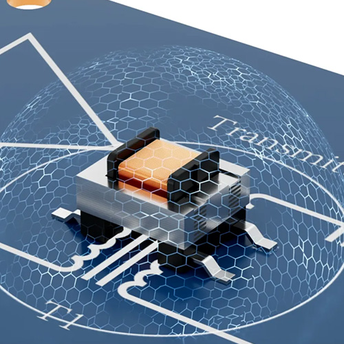
How to wire an audio transformer cannot be decided by counting pins on each side. The primary and secondary provide magnetic coupling and galvanic isolation, while polarity dots identify the relative instantaneous direction of the two windings. Swapping the two leads of one complete winding may leave the signal level apparently normal, but the output polarity becomes inverted by 180 degrees relative to the reference. A single mono path may not make the error obvious. Stereo channels, summed feeds, bridged paths and circuits that use transformer feedback can reveal it as weak bass, an unstable center image or an incorrect feedback direction.
VOOHU audio transformer products include 4-pin, 5-pin and 6-pin configurations. AC impedance, insertion loss, dielectric withstand voltage, package size and winding connections all belong in the selection. During implementation, schematic nets, physical pins and PCB orientation must preserve the same reference so that a channel that passes continuity and produces sound also behaves correctly when combined with the rest of the system.
#1. How to wire an audio transformer: identify windings and polarity first
A winding has no DC positive terminal, but it has relative polarity
An audio transformer transfers an AC signal, so the two ends of a winding are not a DC positive and negative pair. They do, however, have a start and finish. A dot on the schematic normally marks corresponding-polarity terminals. When the instantaneous voltage rises at the dotted primary terminal, the dotted secondary terminal follows the same reference direction. Swapping the two leads of either winding reverses the secondary polarity relative to the primary. Swapping both windings preserves their relationship.
Before wiring, determine which pins belong to the same winding, then use the drawing for the exact product to identify primary, secondary, polarity dots and any taps. A resistance or continuity check can separate the windings, but it cannot establish corresponding polarity on its own. Continuity is therefore only the first check, not proof that the audio polarity is correct.
Four, five or six pins do not define a universal connection
A 4-pin product often exposes two primary and two secondary terminals, but the actual numbering still comes from its drawing. A 5-pin or 6-pin product may include a tap, shield, split winding or another connection. Adjacent pins should never be treated as a winding merely because the package looks symmetrical. Top views, bottom views and PCB land patterns can also mirror the left-to-right orientation.
Clear net names such as PRI_DOT, PRI_RETURN, SEC_DOT and SEC_RETURN retain the intended direction from the schematic into the layout. Mark a center tap separately when one exists. The footprint should preserve Pin 1 and the package outline instead of relying on the direction of printed text. The same reference can then be used for the schematic, footprint, samples and production fixture.
#2. What happens when an audio transformer is wired in reverse
A mono path can pass audio while a stereo or summed result is wrong
In an independent mono isolation path, swapping the two secondary leads usually does not remove the signal. Level and frequency response may look similar because the primary change is relative polarity. If that path is never combined with a reference, listening may not expose the mistake. Once a direct and transformer-coupled path are mixed, two channels are summed to mono, or several microphone feeds carry correlated material, the inverted path can cancel part of the in-polarity path.
Cancellation depends on relative level, delay and frequency content. The closer the two paths are, the deeper the loss after summing. Centered vocals, common low-frequency energy and mono compatibility often make the error noticeable first. A stereo phase check should therefore include separate left/right playback and a mono sum. Two channels that sound normal alone but lose bass or center focus together warrant a polarity trace from the connector through the transformer and following amplifier stages.
Swapping hot and cold conductors in a balanced interface also reverses audio polarity; it is not the same as shorting a winding. The important question is whether the complete system preserves one reference. When a transformer winding participates in an amplifier feedback path, wrong polarity can turn negative feedback into positive feedback and cause oscillation. Such circuits need controlled, current-limited first power-up and confirmation against the intended schematic.
#3. Preserve polarity from the schematic to the PCB and cable assembly
Dots, connector assignments and component Pin 1 must form one chain
Start at the input connector and carry the hot/cold or signal/return names to the primary. Continue the reference from the secondary to the receiving circuit. A balanced interface needs an explicit non-inverting reference. An unbalanced interface needs a defined signal and return terminal. A center tap, when provided, must serve the circuit function shown in the design and should not be grounded simply because it is physically in the middle of the pin row.
Keep the Pin 1 mark visible after assembly and provide primary and secondary test points where the design permits. A stereo board should use the same symbol, footprint orientation and naming convention for both channels. Cable harnesses, adapter boards and fixtures must follow the same convention, because a correct PCB can still be inverted at an external connection.
Split windings require special care for series or parallel connections. Incorrect series phasing can make induced voltages oppose each other. Incorrect parallel phasing can create a large circulating current. Never determine a split-winding connection by energized trial and error when the winding diagram is not confirmed.
#4. Identify corresponding polarity with continuity and low-level waveforms
Use a meter for winding identity and a two-channel scope for direction
First, with power removed, measure DC resistance between pins to group the terminals of each winding and confirm there is no DC continuity between isolated windings. Resistance helps locate connections and obvious opens, but its magnitude alone does not define primary and secondary and does not reveal the phasing dots.
Second, apply a controlled low-level signal, such as a 1 kHz sine wave, to the primary and observe a primary reference and the secondary output simultaneously. Use a differential or isolation-aware measurement arrangement that does not accidentally join the two isolated circuits through grounded probes. Compare positive-going zero crossings and peaks at the terminals identified by the drawing. A result close to 180 degrees calls for a probe-direction check followed by a review of the winding connection and any inverting amplifier stage.
Third, test the transformer with the intended source, load, harness and following circuit. A bench measurement only confirms the polarity between two chosen points; a connector, cable or later amplifier may invert it again. Keep a confirmed board as the reference and compare every channel with a fixed test signal after repair or product substitution.
#5. Selecting a VOOHU audio transformer for the interface and electrical conditions
The connection must serve the circuit function. Do not select a product only by pin count and then force the netlist to fit. The three VOOHU products below provide 4-pin, 5-pin and 6-pin options for an initial comparison of AC impedance, package, insertion loss and dielectric withstand voltage. Each part number is one separate product; its own terminal drawing must be used.
The three products differ in impedance, size, insertion loss and withstand voltage. Begin with source and load conditions, allowed signal level and target bandwidth, then confirm the isolation boundary, mechanical envelope and terminal assignment. For an existing PCB, compare pads, height and every terminal function. Similar appearance or a nominal 600 Ω value does not establish drop-in compatibility.
#6. Add polarity verification from prototype to production
A useful prototype sequence is continuity with power removed, low-level waveform comparison, intended-load testing and stereo or multi-channel summing. Record primary, secondary and tap assignments in the schematic before measuring, and keep the probe direction consistent. Once polarity is confirmed, continue with bandwidth, maximum operating level, load variation and connection transients; correct polarity is not a substitute for complete audio performance testing.
Use the same test signal for left/right channels or repeated boards and record the positive output direction of each path. Add mono summing, center-image and shared low-frequency checks to the usual level and distortion tests. If a repaired channel passes audio but sounds hollow when combined with the reference, direct waveform comparison normally locates the inversion faster than repeated component changes.
A production fixture can apply a short, controlled bipolar pulse or fixed-frequency signal and compare output direction with a qualified reference board. Fixture terminals, probe polarity and software logic must be locked so that the tester cannot become the source of inversion. Recheck pin mapping and channel summing whenever the product, harness or PCB revision changes.
#7. Frequently Asked Questions (FAQ)
How do you wire an audio transformer without reversing polarity?
Identify primary, secondary, dots and taps from the drawing, then preserve them in the schematic net names and PCB Pin 1 marking. A continuity test only groups winding terminals. Finish with a controlled low-level signal and two-channel waveform comparison, followed by a check with the intended harness and load.
Can reversed audio-transformer wiring damage a circuit?
Swapping both ends of one complete winding commonly creates a 180-degree output-polarity inversion and may not damage an independent low-level mono path. Incorrectly paralleling split windings, reversing a feedback winding or connecting a tap to the wrong node can cause circulating current, oscillation or another fault. The result depends on the circuit.
Can a multimeter identify audio-transformer polarity dots?
A normal resistance or continuity function can identify which pins share a winding, but it cannot directly establish the corresponding polarity of two separate windings. Follow the product drawing and confirm direction with a controlled AC signal while maintaining one probe reference.
Why do two channels sound normal alone but lose bass when summed?
One channel may be inverted relative to the other. Correlated content then subtracts when the channels are combined. Centered material and low-frequency energy shared by both channels often reveal it first. Trace polarity through the transformer, connectors, cable and following amplifier.
How should 4-pin, 5-pin and 6-pin audio transformers be selected?
Pin count is only one interface property. Define source and load impedance, winding or tap requirement, allowed insertion loss, dielectric withstand voltage, package and mounting method first. After choosing the product, use its own winding and terminal drawing rather than carrying over a connection from another part.
#8. Preserve overall polarity, not just the presence of audio
Reliable audio-transformer wiring preserves winding identity, corresponding polarity and the system reference from connector to load. Continuity answers which pins form a winding, low-level waveforms answer whether the direction is correct, and a stereo or multi-channel sum confirms the complete signal path. Contact VOOHU technical support to compare 4-pin, 5-pin and 6-pin audio-transformer products against the source, load, interface, isolation and mechanical requirements of your design.
Need a quote, samples or selection support?
Part number WHTT4006 is filled in for you. Add the quantity and lead time and submit. Our FAE team will be glad to confirm the options for your project.
Before you order: samples, MOQ, lead time and import duties in our ordering guide →