Inductor DCR (DC resistance) is the resistance of the winding measured with direct current. It sets the inductor's copper loss, I²R, so at the same current a lower DCR means less heat and higher efficiency. DCR rises with temperature, by about 0.39 % per °C for copper, and the same resistance can be used to sense inductor current without a separate shunt, if an RC network across the inductor is matched to its L/DCR. When you compare parts, first check how each datasheet states DCR: as a maximum, a typical value, or a nominal value with a tolerance. VOOHU molded power inductors start at 0.65 mΩ max (WHYT1040-R15M), and the WHPBU-100710N power bead inductors specify 0.18 mΩ ±10 %.
#What is DCR for an inductor?
DCR is the resistance you would read across the two terminals with a DC ohmmeter: the copper of the winding plus its terminations. It excludes AC losses such as core loss. Datasheets state it in three ways, and they mean different things:
- Maximum (max): a guaranteed upper limit. Use it for a worst-case loss budget. The VOOHU WHYT1040, WHYT1250 and WHYTA0420 datasheets list DCR in a column marked "MAX."
- Typical (typ): the expected value of a typical part, with no guaranteed limit.
- Nominal ± tolerance: a centre value and its spread. The WHPBU-100710N datasheet gives 0.18 mΩ ±10 % for every inductance in the series.
All of these are referenced to a temperature. The VOOHU datasheets cited here state that all test data is referenced to 25 °C ambient.
#How do you calculate inductor DCR loss?
DCR loss is the RMS current squared times DCR: PDCR = IRMS² × DCR. In a buck converter the inductor current is the DC load current plus a triangular ripple, so IRMS² = IDC² + ΔIPP²/12, where ΔIPP is the peak-to-peak ripple. With ripple at 30 % of the DC current, the ripple term adds less than 1 % to the loss, so the DC current dominates.
Suppose a WHYT1040-R15M (0.15 µH, 0.65 mΩ max) carries 30 A DC with small ripple. At its maximum DCR and 25 °C, the copper loss is 30² × 0.65 mΩ ≈ 0.59 W, and the DC voltage drop across the inductor is 30 A × 0.65 mΩ ≈ 19.5 mV. The 30 A is below the part's 45 A typical Irms, and the real loss will be higher once the winding warms up, as the next section shows.
#Inductor DCR vs temperature
Copper has a positive temperature coefficient, so DCR rises in proportion to winding temperature: DCR(T) ≈ DCR25 × [1 + α × (T − 25 °C)], with α about 0.0039 per °C. Richtek's application note DCR Temperature Compensation (AN026) uses 3,930 ppm/°C in its example. In the example above, a 40 °C winding rise (the rise at which WHYT datasheets rate Irms) would take 0.65 mΩ to about 0.75 mΩ and the loss from 0.59 W to about 0.68 W. This is an estimate from the copper coefficient; for a hot-DCR figure on a specific part, ask our FAE team.
#What is the effect of output inductor DCR on a switching power supply?
DCR costs efficiency, because I²R loss grows with the square of the load current; it heats the inductor, which raises DCR further; and it drops a small DC voltage, about 19.5 mV in the 30 A example, which the control loop corrects when the output is sensed after the inductor. At high current, DCR is often one of the largest loss terms in the inductor.
Lower DCR usually comes with lower inductance in the same package. In the WHYT1040 series, DCR rises from 0.65 mΩ max at 0.15 µH to 340 mΩ max at 100 µH, while the rated currents fall. So choose the inductance first from ripple and transient needs, then pick the lowest DCR that meets it; saturation current vs rated current covers the current ratings in detail.
#How does inductor DCR current sensing work?
DCR current sensing measures the inductor current from the voltage across its own winding resistance, so no shunt resistor and no extra loss are needed. Because the winding's inductance and resistance cannot be probed separately, a resistor RX and capacitor CX are placed in series across the inductor. When the time constants are matched, RX × CX = L / DCR, the voltage on CX equals IL × DCR for both the DC and AC parts of the current, as described in Richtek's Comparison of DCR Current Sense Topologies (AN037).
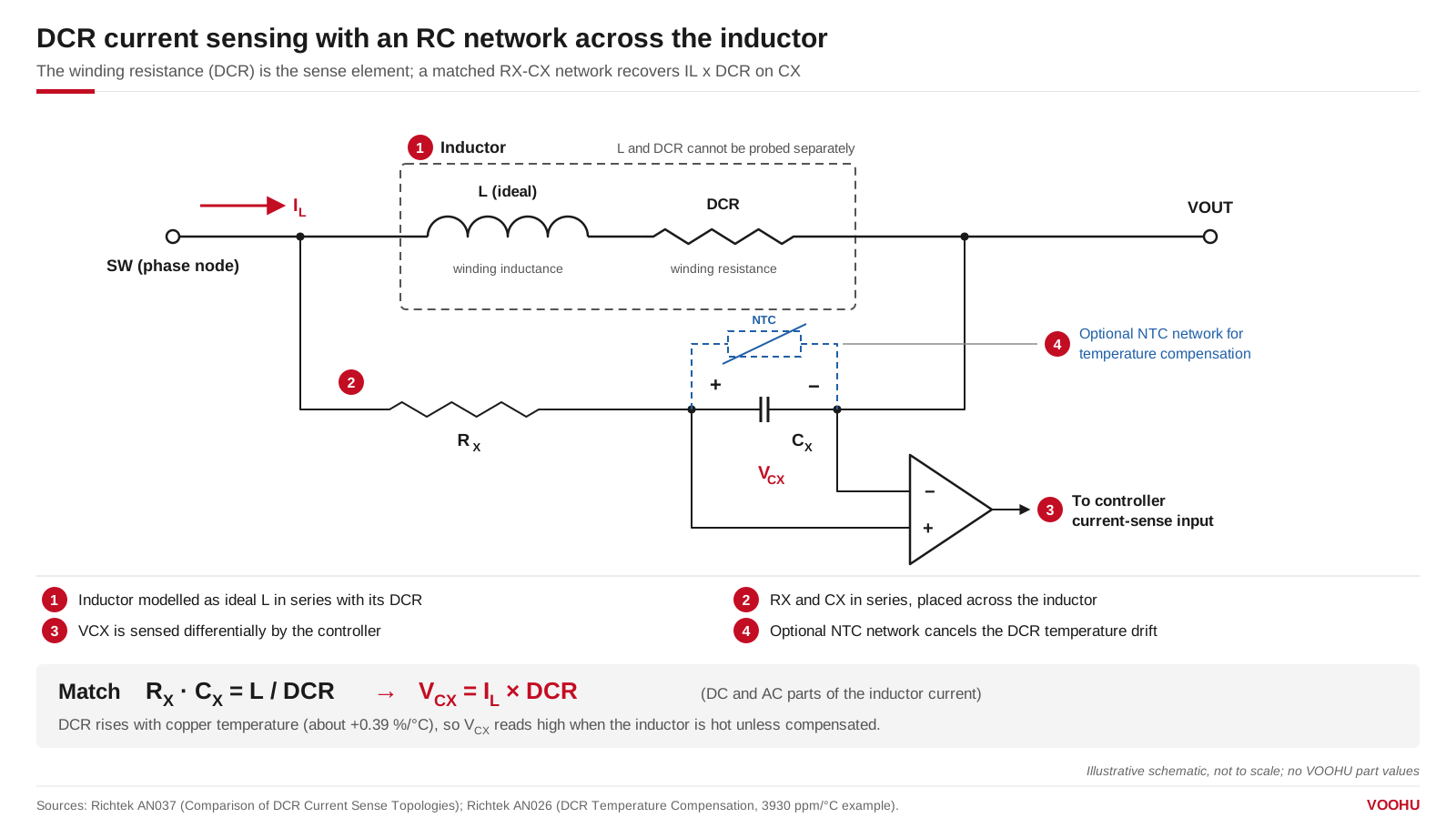
DCR current sensing: with RX × CX = L / DCR, the capacitor voltage VCX follows IL × DCR. An optional NTC network can be added to compensate for the rise of DCR with temperature; where it connects depends on the current-sense topology, so the position shown is one example. Illustrative schematic; no part values.
Three things limit accuracy. First, temperature: as DCR rises about 0.39 % per °C, the controller reads a higher current when the inductor is hot, so designs add an NTC resistor network to cancel the drift (AN026). Second, the DCR value itself: the sensed voltage is I × DCR, so the current reading is only as accurate as the DCR the controller is set to. A maximum DCR is the right figure for a loss budget; for sensing, work from the nominal value and its spread for the exact part. The WHPBU-100710N datasheet states its DCR in that form, 0.18 mΩ ±10 %, and our FAE team can confirm the figures for the other VOOHU parts you are considering. Third, noise: the signal is small (about 19.5 mV at 30 A in the example) and the RC network sits next to the switching node, which makes the sensed signal easy to corrupt (AN037); keep the sense traces short and away from the switching node.
#DCR copper loss vs inductor core loss
DCR covers only the copper loss at DC. Core loss depends on the ripple current, switching frequency and core material, not on DCR, and high frequency adds extra winding loss. At high load current with modest ripple, DCR loss usually dominates; at light load or with large high-frequency ripple, core loss can be larger. Total inductor loss is the sum; our FAE team can help estimate core loss for the VOOHU part you are considering.
#Low DCR power inductors from VOOHU
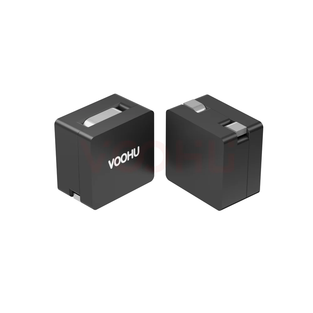
All values are from the VOOHU datasheets, referenced to 25 °C ambient. Isat is the current for about a 30 % inductance drop on WHYT and WHYTA parts and about 20 % on WHPBU parts; Irms and heating current are for a rise of about 40 °C. Because DCR is stated as a maximum on one family and as a nominal value with tolerance on the other, compare parts within a family, not across them.
Where to start: for a high-current rail around 30–45 A, the WHYT1040-R15M and WHYT1250-R22M give sub-milliohm maximum DCR. For a rail where you want a stated DCR spread, for example to plan DCR current sensing, the WHPBU-100710N-R22L0 specifies 0.18 mΩ ±10 %. For rails of a few amps, the WHYTA0420-1R0M offers 1.0 µH with a 6 A typical Irms. Filter the full range in the molded power inductor selector or browse the high-current power bead inductors. For package and layout, see molded power inductor selection and layout; for shielding, shielded vs unshielded power inductors; for multiphase rails, choosing a multiphase buck coupled inductor.
#FAQ
What is the difference between ESR and DCR in an inductor?
DCR is the winding resistance measured with direct current. ESR is the equivalent series resistance at a stated AC frequency, so it also includes core loss and the extra winding resistance from skin and proximity effects. ESR is therefore higher than DCR and rises with frequency. Use DCR for DC copper loss and ESR or core-loss data for the ripple-related loss.
How do you measure the DCR of an inductor?
Use a four-wire (Kelvin) resistance measurement, because sub-milliohm values are smaller than the resistance of ordinary test leads and contacts. Use a low test current so the winding does not heat up, record the temperature, and correct the result to the datasheet reference temperature, which is 25 °C ambient for the VOOHU datasheets cited here.
How low is "low DCR" for a power inductor?
There is no fixed number; judge DCR by the loss it causes at your current. Suppose a 1 V, 30 A rail delivers 30 W: an inductor with 0.65 mΩ max DCR dissipates about 0.59 W at 25 °C, roughly 2 % of the output. On a 3 A rail at the same voltage, the same 2 % budget allows about 10 times more DCR, roughly 6.7 mΩ.
Get samples matched to your current and loss budget
Send your output current, ripple, switching frequency, allowed temperature rise and, if you plan DCR current sensing, your controller part number through our sample request form. Our FAE team can suggest a VOOHU inductor with suitable inductance, DCR and current ratings and check the DCR figures your loss budget or sensing design needs. Samples are available for evaluation, and selected parts are free of charge. Our FAE team will be glad to confirm the options for your project. VOOHU supplies RJ45 and SFP connectors, LAN and PoE transformers and common mode chokes from Suzhou, China, to more than 1,500 customers.
Need a quote, samples or selection support?
Part number WHYT1040 series is filled in for you. Add the quantity and lead time and submit. Our FAE team will be glad to confirm the options for your project.
Before you order: samples, MOQ, lead time and import duties in our ordering guide →