Compiled from both manufacturers' published datasheets. Verify with samples and the PCB footprint before production.
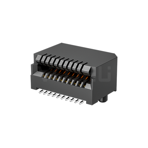
If you buy the Amphenol UE75-A20-6000T and need a second source, you can evaluate the VOOHU WH81-151-Y0002-1 as a functional alternative — verify with samples in your design. The pair share a 20-position, 0.80 mm pitch, right-angle surface-mount SFP host connector format rated −40 to +85 °C, and their drawings give the same nominal 0.50 × 2.00 mm pads and a pair of Ø1.55 mm locating holes on 9.60 mm centres. What separates this Amphenol part from its family members is the digit 6. It selects Amphenol plating option 6: 15 µin of gold on the mating area, and 150–300 µin of matte tin on the solder tails over 50 µin of nickel. The VOOHU drawing title gives the gold as AU 15U. It does not state the tail finish, so ask for that with the samples, before the reflow and solderability checks are set.
#What the Amphenol family drawing and the VOOHU datasheet each specify
The -6000T is covered by the Amphenol family drawing P-UX75-A20-X00XX, revision P, which LCSC hosts with the part listing. Of its three sheets, the first holds the part-number key along with the outline and materials, the second the recommended board layout, and the third the module-side layout. Every dimension appears in inches first and millimetres second, in brackets; this article quotes the millimetres. The VOOHU side is the WH81-151-Y0002-1 datasheet, revision A0, which fits on two pages: the drawing with its material and electrical notes first, then both layouts, board side and module side, on page 2. In the table, "not stated" means the document is silent on that point, which is not the same as saying the feature is absent.
#How to read the Amphenol part number UE75-A20-6000T
Sheet 1 prints the configuration as UX75 − A 20 − X 0 0 X T and explains some of those positions, not all of them. Read against that key, UE75-A20-6000T breaks down like this:
- UE75: the RoHS-compliant version of the UX75 family.
- A20: printed as fixed characters; the key offers no alternatives for them.
- 6: the contact plating option. For UE75 the key allows 2, 3, 5 or 6.
- 0 0: printed as fixed zeros.
- 0 (the last digit): the lubricant option on the mating area, 0 for none and 1 for lubricated.
- T: not defined in the key. Treat it as part of the ordering code and confirm its meaning with your Amphenol source before you write it into a cross-reference.
The plating digit is where a family-level cross-reference goes wrong. Options 2 and 3 put 30 µin of gold on the mating area; options 5 and 6 put 15 µin. Options 3 and 6 finish the solder tails in matte tin, while options 2 and 5 use a 2 µin gold flash. "UE75-A20" on its own therefore describes four different plating builds, and only option 6 pairs 15 µin of mating gold with matte-tin tails. If a second source is assessed against the wrong option, every plating conclusion that follows is about a different part. For purchasing, the fix is in the wording of the approved-vendor entry. A line like this records what the original part is and what is still open on the alternative:
Amphenol UE75-A20-6000T (plating option 6: 15 µin Au mating area; 150–300 µin matte Sn tails over 50 µin Ni; no lubricant). Alternative: VOOHU WH81-151-Y0002-1 (drawing: AU 15U; tail finish to be confirmed by VOOHU in writing). Status: functional alternative, pending sample approval.
#Solder tail finish not stated: what to ask for before the first reflow
On the Amphenol side the tail finish is written down: 150–300 µin (3.81–7.62 µm) of "low whisker" matte tin over at least 50 µin (1.27 µm) of nickel. On the VOOHU side, the drawing title gives the contact gold as AU 15U and says nothing about the tails or the underplate. Neither document gives a reflow profile. For an EMS partner, the fact that usually anchors a solder-process check, the finish the paste has to wet, is printed for one part and not yet for the other. The gap is in the paperwork, so close it with paperwork. Ask for:
- 1.A written statement of the solder-tail finish and its thickness, and of the underplate material and thickness, for the WH81-151-Y0002-1.
- 2.Solderability evidence for the tails, for example a report to IPC J-STD-002 or to the supplier's own method, with the test date.
- 3.A recommended reflow profile, or at least a maximum temperature and time for the connector.
- 4.If your quality plan has a tin-whisker or surface-finish requirement, the evidence that answers it, in the form the plan asks for.
File the answers with the approved-vendor entry, so the next audit finds the tail finish recorded against the VOOHU part number instead of inferred from the Amphenol one. Until then, read the blank literally: "not stated" on a drawing is not evidence of any particular finish, present or absent.
The first article does the rest. Run the current profile, inspect all 20 tail joints by AOI or X-ray, and compare the wetting with boards built on the Amphenol part. On the board itself, keep your land-pattern drawing at the Amphenol pad tolerances (±0.030 mm on width, ±0.05 mm on length), the tighter of the two, and use the same first images to check where the tails, whose envelope is 9.00 mm on the VOOHU drawing against 9.20 mm maximum on the Amphenol one, land on their pads.
#SFP or SFP+? What the two titles do not tell you about speed
The Amphenol drawing is titled "SFP 20 position high speed connector"; the VOOHU drawing is titled "SFP+ CONN 20PIN AU 15U". Neither document states a data rate, and neither publishes insertion loss, return loss or crosstalk for the connector. The "+" in one title and its absence in the other are labels, not ratings, and they should not be used to argue either part up or down. Where the two drawings do agree is the module side: the 9.20 mm and 3.40 / 3.80 mm dimensions, the ten 0.60 mm callouts and the 0.50, 0.90, 1.30 and 3.50 mm callouts are the same, and that is the interface the pluggable module meets. For a 1G SFP port, the evidence that counts is a link and error-count test on your board, using the optical or copper modules that go out with the product, from the cold end to the hot end of its range. If the port runs faster than that, bring the line rate to our FAE team at the start of qualification planning, rather than reading a speed into either title.
#UE75-A20-6000T to WH81-151-Y0002-1: questions to settle, and where the answers come from
#Where the WH81-151-Y0002-1 goes on the board
It sits under the cage at host-side SFP positions: 1G optical uplinks on industrial and access switches, media converters and fiber evaluation boards whose operating range stays inside −40 to +85 °C. The part is the connector only, so the cage remains a separate BOM line. For how the 20 contacts are assigned, see our SFP connector pinout guide.
Reference designIndustrial Ring Switch Reference DesignAn illustrative DIN-rail Gigabit industrial ring switch de…View solution →#FAQ
What is an alternative to Amphenol UE75-A20-6000T?
The VOOHU WH81-151-Y0002-1 is a functional alternative to the Amphenol UE75-A20-6000T — verify with samples in your design. The pair share a 20-position, 0.80 mm right-angle SMT format with 0.50 × 2.00 mm pads, two Ø1.55 mm holes 9.60 mm apart and a −40 to +85 °C rating. Ask VOOHU for the solder-tail finish, which its drawing does not state, before you set up reflow.
What does the 6 mean in UE75-A20-6000T?
It is the contact plating option on Amphenol drawing P-UX75-A20-X00XX. Option 6 is at least 15 µin (0.38 µm) of gold on the mating area and 150–300 µin of low-whisker matte tin on the solder tails, over at least 50 µin of nickel. The last 0 before the T means no lubricant on the mating area.
Is UE75-A20-3000T the same as UE75-A20-6000T?
No. Both have matte-tin solder tails, but on the same Amphenol family drawing option 3 puts 30 µin of gold on the mating area and option 6 puts 15 µin. Option 2, as in UE75-A20-2000T, also has 30 µin of mating gold, but its tails carry 2 µin gold flash instead of tin. Check an alternative against the exact option on your BOM.
Can the WH81-151-Y0002-1 be used in a 1G SFP port?
Neither the VOOHU nor the Amphenol drawing states a data rate, so the answer has to come from your board. The module-side layout carries the same dimensions on both drawings. Test link and error count with your SFP modules across your temperature range, and talk to our FAE team first if the port runs faster than 1G.
#Ask for the tail finish together with the samples
When you ask for WH81-151-Y0002-1 parts through the sample request form, put the full Amphenol part number from your BOM in the message, along with your reflow profile and any solderability or whisker requirement from your quality plan. That gives the reply something concrete to answer in writing. Samples are available for evaluation, and selected parts are free of charge. Our FAE team will be glad to confirm the options for your project. Our FAE team can suggest suitable parts and help check the design — with this connector, confirming the solder-tail finish and underplate, reviewing your land pattern against the Amphenol pad callouts and helping you plan the first-article checks.
VOOHU supplies RJ45 and SFP connectors, LAN and PoE transformers and common mode chokes from Suzhou, China, to more than 1,500 customers.
Other 20-position SFP host connectors are listed in the SFP connector selector, already filtered to connectors.
Related product: WH81-151-Y0002-1 — right-angle surface-mount SFP host connector with 20 contacts at 0.80 mm, gold AU 15U on the drawing, rated −40 to +85 °C.
Need a quote, samples or selection support?
Part number WH81-151-Y0002-1 is filled in for you. Add the quantity and lead time and submit. Our FAE team will be glad to confirm the options for your project.
Before you order: samples, MOQ, lead time and import duties in our ordering guide →