Compiled from both manufacturers' published datasheets. Verify with samples and the PCB footprint before production.
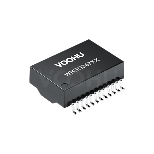
If the Bothhand 24HSS1041A-2 HF sits on a gigabit PoE port in your BOM, the VOOHU WHSG24706-1PTG is a functional alternative — verify with samples in your design. Both are single-port 1000BASE-T transformers in a 24-lead, 1.27 mm-pitch wide-body SMD package with the same pin names on the same pins, a 17.55 × 12.20 × 6.00 mm nominal body, 350 µH minimum OCL and 1500 VAC isolation, and both datasheets refer to IEEE 802.3at. Two things are worth knowing before you order samples. Only the VOOHU datasheet prints a current figure: 720 mA. And the common mode choke sits in a different place: on the line side of the transformer in the Bothhand schematic, on the chip side in the VOOHU one. The WHSG24706-1PTG is also specified for −40 to +85 °C operation.
#24HSS1041A-2 HF vs. WHSG24706-1PTG: what each datasheet prints
The Bothhand values come from its "SMD 1000 BASE-T Single Port Discrete LAN Magnetics" datasheet, revision A00 (19/07): page 1 carries the features, electrical table and schematic, page 2 the outline and suggested pad layout. The VOOHU values come from the WHSG24706-1PTG datasheet, revision A0, with the outline, pads and schematic on page 1 and the electrical table on page 2. Before you use the table, check that the datasheet in your own files is the Bothhand A00 document; if it carries another manufacturer's name, compare against that document instead. Dimensions are in millimetres. Values marked derived are calculated from spans printed on the drawing, not printed themselves.
#Is the Bothhand 24HSS1041A-2 HF 802.3at? Reading the PoE line on both datasheets
Each datasheet gives PoE exactly one line. Bothhand lists "Complying with IEEE 802.3at standard" among the features on page 1 and adds no current, and no OCL value measured under PoE current. VOOHU's item 12 reads "IEEE802.3at compliant performance---720mA Current Capability". That 720 mA is the only current figure on either sheet, and the VOOHU datasheet does not say whether it applies per pair, per channel or to the whole part. So neither line hands you a number you can set straight against your power budget. Texas Instruments' PoE PD Schematic Review Guidelines (SLVAF59) describes the PHY transformer as the component that separates data from power; on a powered port the supply current flows through the center-tapped cable-side windings, so it is your port's real current through those windings that has to be checked on the sample. Write down the current your PSE or PD design actually puts through each pair, and use it for the tests in the checklist below.
Two more numbers matter on a powered port, and they belong in your calculation rather than in a side-by-side verdict. OCL is 350 µH minimum on both parts, but Bothhand measures it with 8 mA of DC bias and VOOHU with 14 mA, so the two minimums were not taken under the same condition; your incoming inspection should use the condition printed for the part you are actually receiving. DCR is 0.9 Ω maximum on the Bothhand sheet and 1.4 Ω maximum on the VOOHU sheet. Conduction loss in a winding scales with the square of the current, so recompute the dissipation with 1.4 Ω and your measured current, then confirm it with a temperature-rise check on a powered sample in its intended enclosure.
#Ethernet transformer common mode choke: line side on Bothhand, chip side on VOOHU
Follow one channel from the PHY to the cable on each schematic and the parts appear in a different order. On the 24HSS1041A-2 HF, TD1+ and TD1− enter a 1CT:1 transformer whose chip-side center tap is TCT1 on pin 1; the cable side of that transformer passes through a two-wire common mode choke and then into a center-tapped winding, and the midpoint of that winding is MCT1 on pin 24. On the WHSG24706-1PTG, TD1+, TD1− and TCT1 first pass together through a three-wire common mode choke, then into a 1CT:1CT transformer, and MCT1 on pin 24 is the transformer's own cable-side center tap. Pin 24 is where your termination network and, on a PoE port, the power path connect, so the DC path behind that pin is not the same in the two parts, even though the pin name is. Your PHY vendor's reference design and layout guide state which magnetics arrangement they were drawn with; read that before you sign off the change, and redraw the library symbol so the schematic shows the choke where the WHSG24706-1PTG actually has it.
Neither datasheet tells you how the move changes emissions or immunity on your product, and this article will not guess. What you can do is measure it under the conditions that matter for a PoE port: power the port at its normal class, run traffic, and repeat the conducted and radiated pre-scans you ran on the Bothhand build with the same cable, link partner and chassis setup. Compare the two sets of results directly. While the port is loaded, log link errors too, since a change in the magnetics is a fair reason to recheck the data path as well as the power path.
#Land pattern and height: 17.00 mm vs. 16.60 mm across the pads
Along each row the two suggested patterns agree: 0.76 mm pads on a 1.27 mm pitch, 13.97 mm from the first lead to the last. Across the rows they differ. Bothhand draws 2.54 mm long pads with their outer edges 17.00 mm apart, which puts the inner edges about 11.92 mm apart (derived). VOOHU prints 12.70 mm inner and 16.60 mm outer, so its pads are about 1.95 mm long (derived). A board laid out to the Bothhand pattern therefore has longer pads that reach further in and 0.20 mm further out on each side (derived). Overlay the WHSG24706-1PTG lead outline, 16.00 ± 0.50 mm across the leads with a 1.10 ± 0.15 mm foot, on your existing pads at both ends of its tolerance and look at where heel and toe land; then let the first sample build show the fillets and any bridging. There is no written FAE confirmation that the Bothhand pads can stay, so treat this as a trial, not a release. For height, both parts are 6.00 mm nominal, but the VOOHU tolerance is ± 0.50 mm against ± 0.25 mm, so check any shield, heat spreader or housing rib above the part against 6.50 mm.
Two paperwork items follow from the datasheets. The Bothhand sheet gives its 1500 V hipot without a duration, while the VOOHU sheet specifies 60 s; if your safety file or incoming test quotes a duration, take it from the VOOHU datasheet for the new part. And the operating range moves from 0 to +70 °C to −40 to +85 °C. The new range contains the 0 to +70 °C of the Bothhand part, but a transformer alone does not extend your product's rating; the rest of the board decides that.
#Checklist before the WHSG24706-1PTG replaces a 24HSS1041A-2 HF
#Where the WHSG24706-1PTG fits
The WHSG24706-1PTG is meant for a single gigabit port that carries power over the data pairs on a board laid out for a 24-lead, 1.27 mm wide-body transformer, including boards that see −40 to +85 °C in operation. If you are also moving a Bourns part to the same VOOHU transformer, our PT61020EL comparison covers that pair; for another Bothhand part, see the NS0013 LF evaluation. For choosing among PoE-rated transformers more broadly, start with our PoE transformer model guide.
#FAQ
What is an equivalent for the Bothhand 24HSS1041A-2 HF?
The VOOHU WHSG24706-1PTG is a functional alternative to the Bothhand 24HSS1041A-2 HF — verify with samples in your design. Both are single-port 1000BASE-T transformers in a 24-lead, 1.27 mm-pitch SMD package with the same pin names, 350 µH minimum OCL and 1500 VAC isolation. The common mode choke is on the line side in the Bothhand schematic and on the chip side in the VOOHU schematic, so check the magnetics against your PHY reference design and compare EMC results.
Is the Bothhand 24HSS1041A-2 HF 802.3at compliant?
Its datasheet (revision A00) lists "Complying with IEEE 802.3at standard" as a feature but gives no current figure. The VOOHU WHSG24706-1PTG datasheet states "IEEE802.3at compliant performance---720mA Current Capability" without saying whether the figure is per pair, per channel or total. Neither statement replaces a temperature-rise test at the current your port actually carries.
Is the 24HSS1041A-2 HF the same part as the 24HSS1041-2 HF?
Treat them as different part numbers. This comparison covers only the 24HSS1041A-2 HF and its Bothhand datasheet, revision A00. Similar numbers such as 24HSS1041-2 HF or 24HSS1041M-2 HF have their own datasheets, so check the exact number and the manufacturer named on the document in your BOM before you use any of the values above.
Can the WHSG24706-1PTG go on a 24HSS1041A-2 HF land pattern?
Treat it as a trial, not a released footprint. Width (0.76 mm) and pitch (1.27 mm) match, so the difference is across the rows: the Bothhand pattern runs to 17.00 mm outside with 2.54 mm pads, and the VOOHU pattern sits between 12.70 mm and 16.60 mm. Check where the WHSG24706-1PTG feet land on your existing pads at the minimum and maximum lead span (15.50 to 16.50 mm), then let a first-article build decide. No written FAE confirmation covers the Bothhand pads.
#Evaluate the WHSG24706-1PTG on your PoE port
To start, request WHSG24706-1PTG samples and attach the port schematic from the RJ45 to the PHY with the PoE power path shown, the current per pair your design delivers, and the land pattern from your 24HSS1041A-2 HF board. Samples are available for evaluation, and selected parts are free of charge. Our FAE team will be glad to confirm the options for your project. Our FAE team can suggest suitable parts and help check the design — for this pair, the chip-side choke against your PHY reference design, the power path through pins 24, 21, 18 and 15, and how the WHSG24706-1PTG leads sit on the Bothhand pads.
VOOHU supplies RJ45 and SFP connectors, LAN and PoE transformers and common mode chokes from Suzhou, China, to more than 1,500 customers.
To compare other 24-lead, 1.27 mm parts that list the same current figure, open the LAN transformer selector with those filters already applied.
Related product: WHSG24706-1PTG, a single-port 100/1000BASE-T SMD LAN transformer: 24 leads at 1.27 mm, 17.55 × 12.20 × 6.00 mm nominal body, OCL of at least 350 µH at 14 mA DC bias, isolation tested at 1500 VAC for 60 s, IEEE 802.3at compliant performance with a 720 mA current capability as stated in its datasheet, operating range −40 to +85 °C.
Need a quote, samples or selection support?
Part number WHSG24706-1PTG is filled in for you. Add the quantity and lead time and submit. Our FAE team will be glad to confirm the options for your project.
Before you order: samples, MOQ, lead time and import duties in our ordering guide →