The following is a detailed analysis of the differences and design considerations between voltage-based PHY and current-based PHY in network transformer applications, combined with actual scenarios and technical requirements:
────────────────────────────────────────────────
1. Differences between voltage-based PHY and current-based PHY
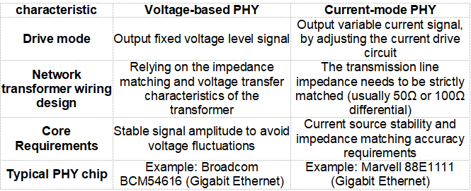
Summary of key differences
- Driving principle
- Voltage-type PHY: directly outputs a specific voltage signal (such as a 2.5V swing).
- Current-type PHY: driven by a current source, the output current is determined by the line impedance and the required voltage.
- Network transformer selection
- Voltage type: Focus on the transformer primary/secondary voltage ratio (e.g. 1:1 or 1:2).
- Current type: The impedance of the transformer needs to be matched (such as 1:1CT, center tap is used for common mode rejection).
- Impedance matching design
- Voltage type: A terminating resistor (such as a 100Ω differential resistor) may be required on the secondary side of the transformer.
- Current type: A matching resistor network (such as a 25Ω resistor in series + a 100Ω resistor in parallel) needs to be set on the PHY side.
────────────────────────────────────────────────
2. Differences in network transformer wiring design
1. Typical wiring of voltage-based PHY
- Wiring diagram:
PHY TX ± → Transformer primary ± → Secondary ± → RJ45 (center tap connected to filter capacitor + VDD)
Design points:
- The center tap needs to be connected to the PHY power supply (e.g. 2.5V) through a capacitor (e.g. 0.1μF).
- The secondary side needs to terminate the differential line with a 100Ω resistor to suppress signal reflection.
2. Typical wiring of current-mode PHY
- Wiring diagram:
PHY TX ± → matching resistor → transformer primary ± → secondary ± → RJ45 (center tap connected to common mode inductor)
- Design points:
- The PHY side requires impedance matching through a series resistor (e.g. 25Ω) and a parallel resistor (e.g. 100Ω).
- The center tap should be connected to a common mode inductor or directly to ground (depending on the PHY manual requirements).
────────────────────────────────────────────────
3. Design considerations
1. Notes on voltage-based PHY
- Power supply stability: The center tap power supply needs to be low-noise. It is recommended to use LDO power supply and add decoupling capacitors (such as 10μF+0.1μF).
- Termination resistance accuracy: 100Ω differential resistors must have 1% accuracy to avoid clock jitter caused by signal reflection.
- Signal amplitude debugging: The oscilloscope detects whether the signal swing meets the standard (such as 1V peak-to-peak value) to prevent insufficient PHY driving capability.
2. Notes on current-mode PHY
- Impedance matching network: Design matching resistors strictly according to the PHY manual (example: 25Ω series + 100Ω parallel).
- Current source protection: To avoid output short circuit, PHY may be damaged due to overcurrent.
- Common-mode noise suppression: The center tap increases the common-mode inductance (e.g. 10mH) to improve EMI performance.
3. Common points of attention
- Transformer selection: It must support the operating frequency (10/100/1000BASE-T corresponds to different frequency bands).
- PCB wiring rules:
- Differential lines are strictly equal in length (±5 mil), evenly spaced, and impedance error is controlled to be ≤10%.
- The distance between PHY and transformer is ≤50mm to reduce path loss.
- EMC design:
- Place an isolated ground plane near the network transformer.
- Add TVS diodes to prevent surge damage.
────────────────────────────────────────────────
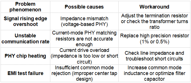
4. Common Errors and Solutions
────────────────────────────────────────────────
V. Conclusion
- Voltage-type PHY: suitable for low-cost, medium- and low-speed scenarios (such as 10/100M). The circuit design is simple but requires strict voltage regulation.
- Current-type PHY: used in high-speed/high-precision scenarios (such as Gigabit Ethernet), requiring precise impedance matching and noise suppression.
- Core principles:
- Design the network transformer peripheral circuit according to the PHY chip manual.
- Focus on Signal Integrity (SI) and Electromagnetic Compatibility (EMC).
Select the appropriate PHY type based on actual needs and use simulation tools (such as ADS/HFSS) to optimize performance during design.
Need a quote, samples or selection support?
Fill in the part number, quantity and lead time. Samples are available for evaluation, and selected parts are free of charge. Our FAE team will be glad to confirm the options for your project. Not sure about a parameter? Enter "Not sure". Need something non-standard? Choose Custom Design.
Before you order: samples, MOQ, lead time and import duties in our ordering guide →