On an RJ45 jack with integrated magnetics, contacts 1 to 8 still follow the TIA-568 cable-side pinout, but the PCB pins connect to the PHY side of the internal transformers, so the PCB pinout is set by each part's schematic. On three VOOHU tab-down jacks, pin 1 is TD+ on one, the common center-tap supply (VCC) on another and TD1+ on the third, and it sits in a different place each time. A plain RJ45 jack is simpler: its PCB pins 1 to 8 connect straight to contacts 1 to 8. On both types, LED pins are numbered after the signal pins and vary by part, so build every footprint from the datasheet of the exact part number, drawn from the component side.
#What is the pinout and schematic of an RJ45 jack with integrated magnetics?
A jack with integrated magnetics (sometimes called a MagJack, a Bel Fuse trademark) puts the LAN transformers, and usually the termination, inside the RJ45 housing. Contacts 1 to 8 still follow the cable-side table further down, but they connect to the cable side of the internal transformers. The PCB pins connect to the PHY side, so their numbers no longer map one to one to the contact numbers. Three VOOHU tab-down jacks show how much the PCB pinout can differ:
Three points follow for layout:
- Find pin 1 by name, not by position. On these three parts it is a different signal and sits in a different place each time.
- Check the termination before you add your own. All three already include the 75 Ω and 1000 pF network that many designs place on the board.
- For PoE, use the center-tap pins. On the SYT111Q334AB2A2DP057, pins 11 to 14 are the cable-side center taps. The datasheet states "balanced DC line current 600mA max. 57V DC continuous" and describes the part as PoE magnetics "acc. to IEEE802.3at for PSE or PD applications".
The 1000BASE-T pinout also shows why pairs must stay together: on the SYT111Q066AA2A1D, pair 2 uses PHY-side pins 4 and 7, matching contacts 3 and 6. For the trade-offs between integrated magnetics and a discrete transformer plus a plain jack, see our guide to integrated or discrete magnetics. To list only jacks with integrated magnetics, open the RJ45 selector with the integrated magnetics filter; it covers several hundred part numbers.
#How are RJ45 pins 1 to 8 numbered?
The eight contacts that touch the plug are numbered 1 to 8 in the standard 8P8C order. Their use on the cable side is fixed by ANSI/TIA-568 and IEEE 802.3, whatever jack you choose:
Cat5e, Cat6 and Cat6A jacks use the same numbering; the category describes transmission performance, not the pin order.
On a plain RJ45 jack, the PCB pins carry the same numbers. The datasheet schematic of the VOOHU SYT561188AB1A1DB4, for example, wires PCB pins 1 to 8 straight to contacts J1 to J8. Extra pins for LEDs, and the shield tabs, come on top of those eight.
#Where is pin 1 on a tab-up and a tab-down RJ45 jack?
Look straight into the jack opening:
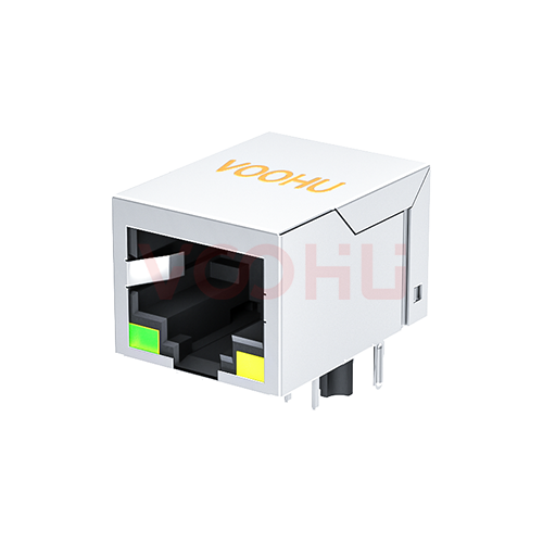
- Tab-down (latch slot at the bottom, next to the board): contacts run 1 to 8 from left to right. The SYT59A31882201221101 datasheet shows this order, with the LEDs in the two lower corners, and so do the three jacks with integrated magnetics above.
- Tab-up (latch slot at the top, away from the board): the contact row is rotated 180° and runs 8 to 1 from left to right. The SYT561188AB1A1DB4 datasheet shows this order, with the LEDs in the two upper corners.
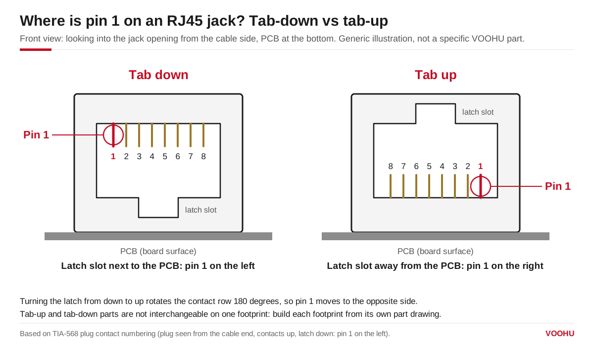
Flipping the latch from down to up moves pin 1 to the opposite side of the jack, so tab-up and tab-down parts cannot share one footprint.
Because the contact order is mirrored, a tab-up jack cannot drop into a tab-down footprint. Our article on tab-up vs tab-down jacks walks through that change pin by pin.
#How do you read the RJ45 footprint in a datasheet?
The pin numbers that matter for layout are the ones on the recommended PCB layout, and the first thing to check is the viewing side. The datasheets of the SYT561188AB1A1DB4 and the three jacks with integrated magnetics above label the drawing "recommended PCB layout viewed from component side"; the SYT59A31882201221101 datasheet does not state the view, so ask our FAE team to confirm it before you build the footprint. If your CAD library is built from a bottom (solder-side) view, the pin order comes out mirrored.
On most of these jacks the signal pins sit in two staggered rows; the SYT111Q334AB2A2DP057 adds two short rows for its PoE pins 11 to 14. Two shield-tab holes and two plastic locating posts fix the part, and on the three jacks with integrated magnetics the LED pins form the row closest to the opening. Hole sizes and spacing differ by part, so take them from the drawing.
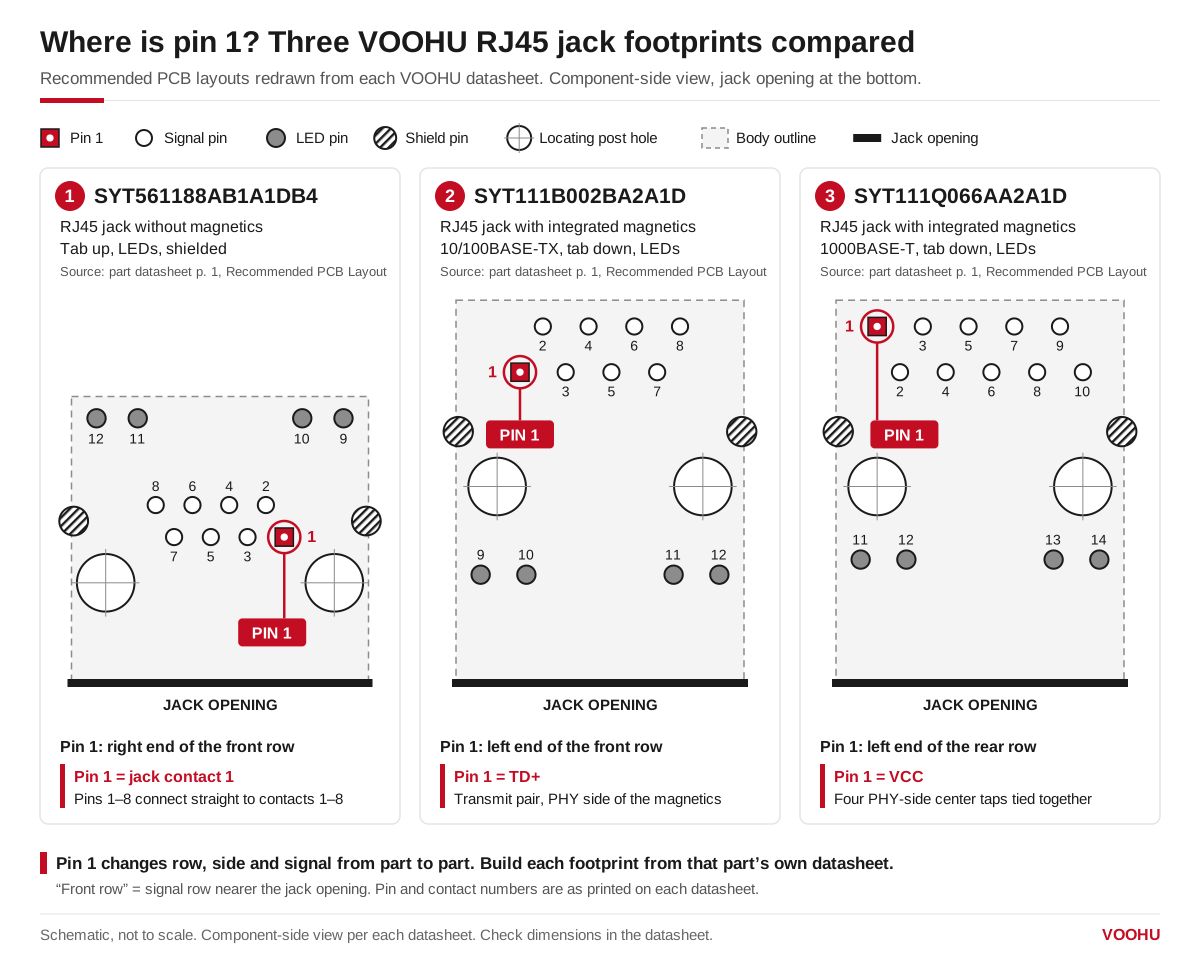
Pin 1 changes row, side and signal across a plain VOOHU jack and two VOOHU jacks with integrated magnetics (jack contact 1, TD+, center-tap VCC), so build each footprint from that part's own datasheet.
Do not reuse a footprint across part numbers, even within one series. The SYT111B002AA2A1D and SYT111B002BA2A1D are both tab-down 10/100 jacks with integrated magnetics and read the same on the schematic, yet the distance from the LED pin row to the locating-post centerline is 4.06 mm on one and 4.90 mm on the other.
#Which pins are the RJ45 LED pins, and what do the LEDs mean?
There is no standard LED numbering for RJ45 jacks. Each part numbers its LED pins after its own signal pins, and the anode can sit on the inner or the outer pin. Five VOOHU jacks, as drawn in their datasheets (anode → cathode):
The left and right colors also swap between parts, so check them as seen from the front panel. For the current-limiting resistor, use the LED data on the datasheet: on the SYT111Q066AA2A1D, the green LED is 568 nm at 20 mA with a forward voltage of 1.85 to 2.45 V, and the yellow LED is 585 nm at 20 mA with 1.7 to 2.2 V. The RJ45 selector lists more than 20 LED color combinations, plus parts with no LEDs.
What the LEDs show, such as link, speed or activity, is not set by the jack. It depends on how the PHY or switch drives each LED pin and how its LED modes are configured, so a green LED can mean link on one device and activity on another. To read the LEDs on a product, check its manual; to design them, wire each LED to the PHY LED output you configure, using the jack datasheet for anode and cathode.
#Footprint checklist before you release the board
- 1.Use the datasheet of the exact part number. Parts in one series can have different footprints.
- 2.Confirm the viewing side of the layout drawing (component side or solder side) and match it to your CAD library.
- 3.Find pin 1 from the drawing and the pin names, not from its position on another part.
- 4.On a plain jack, route contacts 1-2 and 3-6 (10/100) or all four pairs (1000BASE-T) to the transformer, keeping each pair together.
- 5.On a jack with integrated magnetics, connect by signal name (TD±, center tap, VCC, GND) from the schematic, connect the PHY-side center taps as your PHY's reference design shows, and check whether termination is built in.
- 6.Check each LED's anode and cathode pins, and which color is on the left as seen from the front panel.
- 7.Confirm with the datasheet or our FAE team how the shield tabs and any GND pin should be grounded in your design.
#Which VOOHU RJ45 jack should you start from?
These four PCB-mount RJ45 connectors are good starting points:
For a plain tab-down jack, the SYT59A31882201221101 is shown above. The full range, with filters for tab direction, magnetics, data rate, PoE and LEDs, is in the RJ45 connector selector.
SolutionEthernetInterface + magneticsView solution →#FAQ
Is pin 1 of an RJ45 jack on the left or the right?
It depends on the latch. Looking into the opening, pin 1 is on the left of a tab-down jack (latch slot next to the board) and on the right of a tab-up jack. On the PCB footprint, find pin 1 on the datasheet's layout drawing and note whether it is drawn from the component side.
Why doesn't the PCB pinout of a jack with integrated magnetics map one to one to contacts 1 to 8?
Because its PCB pins connect to the PHY side of the internal transformers, not to the contacts. On VOOHU parts, pin 1 is TD+ on the SYT111B002BA2A1D, the PHY-side end of the pair on contacts 1 and 2, but the common center-tap supply (VCC) on the SYT111Q066AA2A1D. Always follow the schematic of the exact part.
Does Ethernet require magnetics?
For a BASE-T port on an RJ45 jack, yes in practice. IEEE 802.3 requires the cable side of a 10BASE-T to 10GBASE-T port to be isolated from the device and to pass one of its electrical strength tests, such as 1500 V rms for 60 s, and the LAN transformer provides that isolation while it passes the data signal. The magnetics can be a discrete LAN transformer next to a plain jack, or built into the jack. Single-pair Ethernet is different: its interfaces can use capacitive or transformer coupling, so follow the PHY vendor's guidance there.
What is the difference between an RJ45 jack with and without magnetics?
A plain RJ45 jack connects its PCB pins straight to contacts 1 to 8, so you place a separate LAN transformer, and usually the termination, on the board. A jack with integrated magnetics carries the transformers, center taps and usually the termination inside, so its PCB pins are PHY-side signals and its footprint is different. The two are not interchangeable on one footprint; our guide to integrated or discrete magnetics compares the trade-offs.
Should there be a ground plane under Ethernet magnetics?
Not under a discrete LAN transformer. PHY vendors' layout guides, such as Analog Devices' layout notes for its ADIN1300 PHY, say no metal layers should sit directly underneath the transformer, to limit noise coupling across it, and call for an isolation gap between chassis ground and the PHY ground. With integrated magnetics the transformers sit inside the jack, so follow the keep-out drawing in the jack datasheet, where there is one, and your PHY vendor's layout guide.
#Get a footprint check before you release the board
Send us the part number you plan to use, or the PHY and the port you need (data rate, PoE, LEDs, tab direction), through the sample and support request form. We can suggest a VOOHU PCB-mount RJ45 connector, with or without integrated magnetics, and check pin 1, the LED pins and the shield connection against your footprint. Samples are available for evaluation, and selected parts are free of charge. Our FAE team will be glad to confirm the options for your project.
VOOHU supplies RJ45 and SFP connectors, LAN and PoE transformers and common mode chokes from Suzhou, China, to more than 1,500 customers.
Need a quote, samples or selection support?
Part number SYT111Q066AA2A1D is filled in for you. Add the quantity and lead time and submit. Our FAE team will be glad to confirm the options for your project.
Before you order: samples, MOQ, lead time and import duties in our ordering guide →