Gigabit Ethernet Surge Protection Circuit: ESD and Surge Reference Design (Current-Mode PHY) · Standard reference design schematic (D1.0)
Key design points of the Gigabit Ethernet port surge protection circuit
Scope
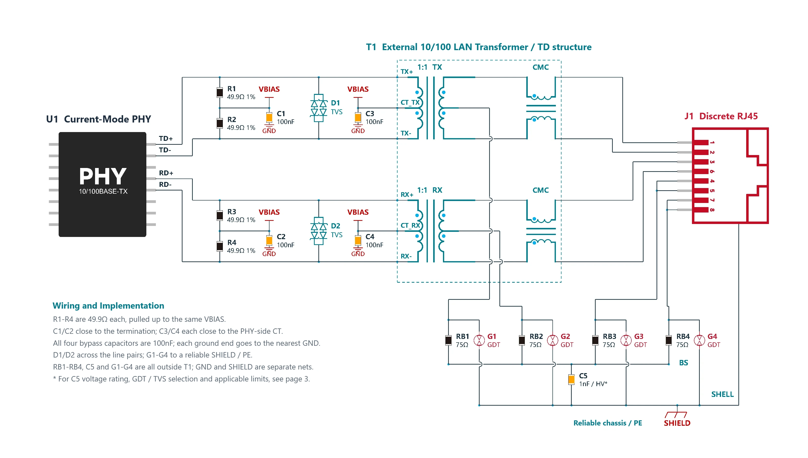
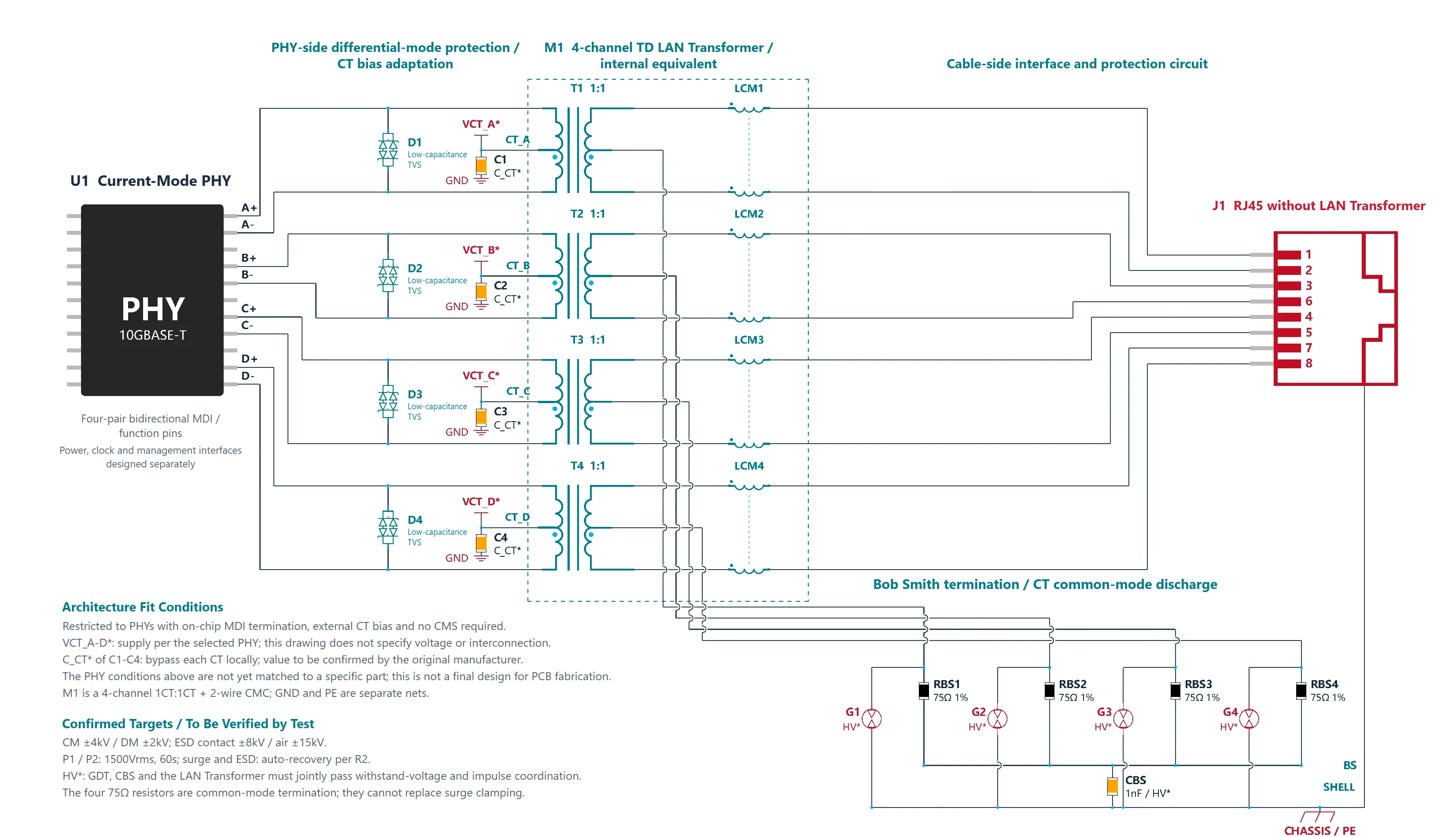
Non-PoE 1000BASE-T with four bidirectional pairs; discrete RJ45 + external TD LAN transformer, with a reliable chassis ground/PE. Applies to current-mode PHYs with external split termination, AC-grounded midpoints and CTs that require bias.
Termination and bias
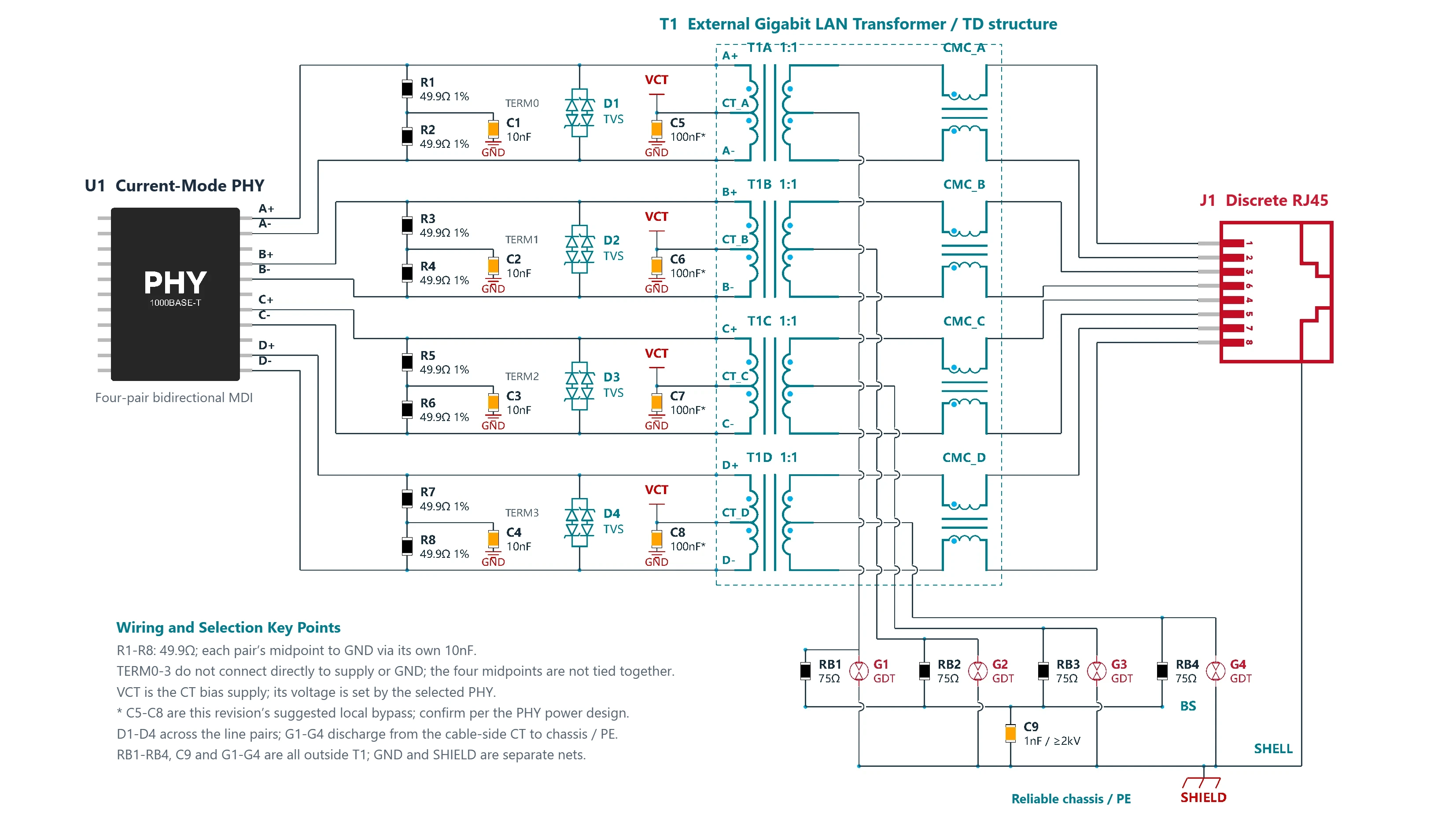
R1–R8 are 49.9Ω each. The midpoint of each pair connects to GND through its own 10nF; the midpoints do not connect directly to a supply or to GND. The PHY-side CTs connect to VCT, with the voltage set by the PHY. C5–C8, 100nF each, are this version's recommendation for local bypassing.
Magnetics and contacts
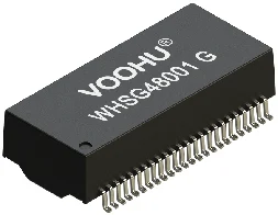
T1 contains four 1:1 isolation transformers + cable-side CMCs. A/B/C/D connect to RJ45 contacts 1/2, 3/6, 4/5 and 7/8 respectively. All pairs carry data, so 4/5 and 7/8 are not shorted.
Staged protection
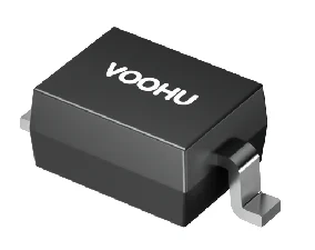
D1–D4 are PHY-side low-capacitance bidirectional differential-mode TVS diodes, each across one data pair. G1–G4 each connect from a cable-side CT to SHIELD, tapping in before the 75Ω resistor; SHIELD connects to a reliable chassis/PE.
Common-mode termination and implementation
The four CTs each join BS through RB1–RB4 (75Ω), and BS connects to SHIELD through C9 (1nF, ≥2kV); the RJ45 metal shell connects to the same net. GND and SHIELD are separate nets. Select the protection parts according to the PHY and the test conditions; see page 3 for parameters and basis.
How to read the Gigabit Ethernet port surge protection schematic
R1–R8: 49.9Ω; the midpoint of each pair connects to GND through its own 10nF.
TERM0–3 do not connect directly to a supply or GND, and the four midpoints are not connected to each other.
VCT is the CT bias supply; its voltage is set by the selected PHY.
* C5–C8 are this version's recommendation for local bypassing; confirm them against the PHY power design.
D1–D4 are connected across the line pairs; G1–G4 discharge from the cable-side CTs to chassis / PE.
RB1–RB4, C9 and G1–G4 are all outside T1; GND and SHIELD are separate nets.
Function terminal names are not package pin numbers; the RJ45 numbers are cable contacts. A solid dot marks a connection, a dot beside a winding marks the dotted (same-polarity) terminal, and a crossover arc means no connection. See page 3 for protection parameter selection.
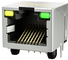
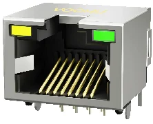
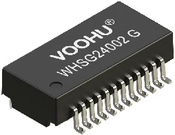
The part numbers above are the VOOHU parts listed under "Product illustrations" in this reference design PDF, provided for selection reference. Verify the final part numbers item by item against the PHY vendor documentation and the circuit parameters.
Need a quote or samples for these parts? Send your quantity and PHY model to a VOOHU FAE to check the part selection against this reference design.
Applies only to the termination architecture in this schematic. Each pair uses 2×49.9Ω (±1%), with the midpoint to GND through 10nF. The four midpoints are not connected directly to each other, nor directly to VCT or GND. Separate midpoints reduce common-mode coupling; the differential termination is about 100Ω.
E1 sheet 7; Resistor tolerance is an engineering recommendation
VCT / C5–C8
Four 100nF*, outside T1
The four PHY-side CTs connect to the bias supply. The 88E1111 example uses 2.5V; this cannot be applied directly to other PHYs. *The 100nF near each CT is this version's engineering bypass recommendation; confirm the capacitance, quantity and supply filtering against the selected PHY and the PCB power design.
1:1 isolation transformer + cable-side CMC form the TD structure; keep the dotted terminals and polarity matched. The magnetics must meet the target PHY's insertion loss, return loss, inductance, balance and insulation requirements. Also check the withstand capability of the windings and CMC in the CT surge path.
Structure: E3 Figure 7; Parameters per PHY/magnetics vendor documentation
D1–D4 / bidirectional TVS
4 differential-mode protection channels
Connected across the P/N of each pair on the PHY side, close to the LAN transformer. Choose low-capacitance parts suited to Gigabit signals. VRWM covers the normal differential swing; clamping and energy at the actual surge current must match the PHY's transient withstand. There is no universal voltage value that can be applied directly.
E4 Figure 4; Specific part number and parameters to be selected
G1–G4 / GDT
4 paths, outside T1
Each cable-side CT connects to SHIELD/PE through a GDT, before the 75Ω resistor. The GDT's sparkover voltage, impulse current, residual voltage and differences in firing behavior must be coordinated with the magnetics, the TVS and the port insulation test.
Local connection: E5 p. 8; Non-PoE combination: engineering design
RB1–RB4 / 75Ω
Four, outside T1
Each of the four cable-side CTs goes through a series 75Ω resistor to BS for common-mode termination. These resistors cannot replace the GDT/TVS. Calculate the pulse power before the GDT fires and from the residual surge. ±1% is an engineering selection recommendation.
Connection and value: E3 p. 11; Pulse check: engineering requirement
C9 / 1nF, ≥2kV
One, outside T1
BS connects to SHIELD through a high-voltage capacitor, giving high-frequency common-mode current a return path. ≥2kV is a recommended voltage rating for the reference part; confirm it against the specific AC/DC rating, insulation and residual surge. It does not mean the system can withstand a 2kV or higher surge.
E3 p. 11; Final insulation coordination to be checked separately
J1 / GND / SHIELD
Discrete RJ45; separate nets
A/B/C/D map to 1/2, 3/6, 4/5 and 7/8. SHELL, the GDTs and C9 return to a reliable chassis/PE. GND is only on the PHY side; this schematic has no fixed GND-SHIELD coupling branch. Add the actual solder tabs, LEDs and complete PHY peripheral circuitry according to the selected parts.
E3; Reliable chassis/PE to be confirmed by the user; Mapping in this schematic
Vendor documentation and scope of use
E1 · Altera Cyclone IV GX development board, 150-0311002-B1 Rev.B, 2010-03-03. Schematic sheet 7 of 15: 88E1111 with two 49.9Ω resistors per pair, each midpoint to ground through 0.01µF. Only the Gigabit termination example is adopted; the board's system-level grounding is not carried over.
E2 · Marvell 88E1111 datasheet, MV-S100649-00 Rev.M, 2020-08-31. p. 190 §4.4.3, Table 125: the CT supply for the external magnetics is 2.5V. This value applies only to the 88E1111; this generic schematic keeps VCT, which is set by the selected PHY.
E3 · Texas Instruments TIDA-00204 design guide, TIDU832B, 2017-07. p. 11 §2.3.1.1.3, Figure 7: the four cable-side CTs each go through 75Ω, then through a shared 1000pF capacitor to chassis, with a recommended voltage rating of ≥2kV. Only the cable-side network is adopted; its voltage-mode PHY termination and test levels are not copied.
E4 · Semtech Ethernet Protection Methodology, 2020-02-19. Figure 4 and conclusions: the TVS goes across the pair, on the PHY side, and is sized by the PHY damage threshold and the surge current. This page does not use it as the basis for promising a protection rating for this version.
E5 · Littelfuse General Port Protection, 2024, p. 8. The original figure on p. 8 is for PoE++; only the local topology of four cable-side CTs discharging to ground through GDTs is borrowed here. Porting it to non-PoE and combining it with E1/E4 is engineering design, and system-level performance has not been verified.
Limits of use
This schematic uses the termination from a Gigabit current-mode example, combined with GDT and differential-mode TVS protection. Each stage has a published vendor basis, but the combined design has not been system-tested, so no kV protection rating can be claimed directly. Layout and protection validation: design the MDI for 100Ω differential impedance; place the termination right next to the PHY and the TVS diodes close to the magnetics, with short branches that are symmetrical within each pair. Keep the GDT-to-PE return path short and wide, and keep it separate from the PHY-side routing and reference planes. After defining the ESD/surge level, waveform, coupling method, source impedance and pass criteria, verify the link, signal integrity, residual voltage, part pulse stress and insulation. This version does not cover PoE, direct lightning strikes or sustained power-frequency faults. The products shown have not been confirmed as a match. The reference circuit is for design and part selection; final connections, part parameters and protection performance depend on the actual parts selected and on system-level validation results. This version has completed document, schematic and connection data review; no native EDA ERC, prototype protection testing or system certification has been performed.
Gigabit Ethernet port surge protection FAQ
Can the termination midpoints of a Gigabit current-mode PHY connect directly to VCT or GND?
No. Each pair uses a 2×49.9Ω (±1%) split termination, and each midpoint connects to GND through its own 10nF. The four midpoints are not connected to each other, nor directly to VCT or GND; separate midpoints reduce common-mode coupling, and the differential termination is about 100Ω. This approach comes from the 88E1111 Gigabit termination example on an Altera development board and applies only to the termination architecture in this schematic.
The 88E1111 connects its CTs to 2.5V. Can I copy that for another Gigabit PHY?
Not directly.2.5V is only the CT supply value for the external magnetics given in the Marvell 88E1111 datasheet. The generic schematic keeps VCT, with the voltage set by the selected PHY. C5–C8 (100nF) beside each CT are this version's engineering bypass recommendation; confirm the capacitance, quantity and supply filtering against the selected PHY and the PCB power design.
Can 4/5 and 7/8 on a Gigabit port be shorted in pairs as on a 10/100 Mbps port?
No. 1000BASE-T carries bidirectional data on all four pairs. A/B/C/D connect to RJ45 contacts 1/2, 3/6, 4/5 and 7/8 respectively, and 4/5 and 7/8 are not shorted. Instead, the common-mode termination takes the four cable-side CTs, each through a series 75Ω resistor (RB1–RB4), to BS, and BS connects to SHIELD through C9 (1nF, ≥2kV). This follows the cable-side network in TI TIDA-00204.
C9 is marked ≥2kV. Does that mean the Ethernet port can withstand a 2kV surge?
No.≥2kV is only a recommended voltage rating for the reference part; confirm it against the specific AC/DC rating, insulation and residual surge. It does not mean the system can withstand a 2kV or higher surge. The GDT and TVS combination has not been system-tested, so no kV rating can be claimed; define the ESD/surge level, waveform and pass criteria, then validate.
Where do the G1–G4 gas discharge tubes connect? Can they damage the LAN transformer?
Each one connects at a cable-side CT, before the 75Ω resistor, and goes through the GDT to SHIELD/PE, outside T1. This topology is borrowed from a Littelfuse PoE++ example; porting it to non-PoE is engineering design. The CT surge path passes through the windings and CMC, so check the withstand capability of the magnetics separately, and coordinate the GDT sparkover voltage, impulse current and residual voltage with the magnetics and the TVS.
Hello! Thank you for using the VOOHU official platform
To provide you with more accurate technical support, please fill in the following information
*We promise to strictly keep your information confidential, only for material delivery and follow-up technical support
Submission Successful
Thank you for your trust and support. Our engineering team will contact you within 1 business day to provide product selection recommendations and technical support
Talk to VOOHUWeekdays 8:30–18:00 (UTC+8) · first reply within 1 business day
Keep the site secure and working, and remember your language and cookie choice.
VOOHU
02
Analytics
Show us which pages are visited and how the site performs, so we can improve it.
Google Analytics · Ahrefs · VOOHU
03
Ad measurement
Measure which of our campaigns bring visitors to VOOHU.
Google Ads
04
Ad personalization
Show you more relevant VOOHU ads on other websites.
Google Ads · Meta · LinkedIn
In the EEA, the UK and Switzerland, analytics and advertising stay off until you allow them. Elsewhere, Google Analytics and Google Ads measurement are on by default, and ad personalization stays off until you allow it.
Changes save automatically
Privacy
Your privacy, your choice
We use cookies to run this site, understand how it’s used and measure our campaigns. Choose what’s on, and change it anytime in Cookie settings. Cookie Policy
✓Preferences saved. Change them anytime under Cookie settings in the footer.
WhatsApp Chat
Typically replies in minutes
Support
Hi! Thank you for connecting with VOOHU! How can we help you today?
Online now
We’ll open WhatsApp (mobile app or WhatsApp Web) with your message pre-filled.