A 2.5G, 5G or 10G RJ45 MagJack (RJ45 jack with integrated magnetics) is chosen from the same kind of datasheet as a Gigabit one, but the line that decides it moves: the frequency range over which insertion loss and return loss are specified. On VOOHU datasheets that range runs to 80–100 MHz on a Gigabit example, 125–200 MHz on 2.5G parts, 250 MHz on a 5G part and 400–500 MHz on 10G parts. Check that range against the magnetics requirements of your PHY first. Then check the PoE line (current at 57 V DC continuous), the Hi-Pot test condition, port count and tab direction, LEDs, contact plating and temperature range, and compare the pinout drawing with your existing footprint. VOOHU offers MagJacks at all three rates, with and without PoE; the table below lists a representative of each.
This guide is for engineers moving a design such as a Wi-Fi 7 access point, a NAS or a switch uplink from a Gigabit jack to a multigig one, and for the buyer who has to specify the new part. If you are still deciding between a MagJack and a discrete transformer with a plain jack, start with integrated or discrete RJ45 connectors. Discrete parts are on the 2.5G and 5G Base-T LAN transformer and 10G Base-T LAN transformer pages.
#2.5G vs 1G Ethernet: what changes in the MagJack?
The connector does not change: eight contacts, four pairs, the same RJ45 plug. What changes is the band the PHY uses. 2.5GBASE-T and 5GBASE-T (IEEE 802.3 Clause 126) and 10GBASE-T (Clause 55) all run on four pairs at once, and each step up in rate puts the signal at higher frequencies. The magnetics inside the jack have to keep insertion loss low and return loss high across that wider band, so a multigig datasheet specifies its loss lines further up the spectrum.
That is also how you tell a 2.5G RJ45 connector from a Gigabit one when the outline gives no clue. Both VOOHU parts below are 1×1 jacks, yet their datasheets differ where it matters:
So the first check is quick: read the rate in the drawing title, then read how far up the loss lines go. A jack whose return loss stops at 80 MHz was specified for a Gigabit band, not a 2.5G one, however similar the outline.
#What should a 2.5G, 5G or 10G MagJack datasheet show?
- The rate in the drawing title. VOOHU drawings name it, for example "TAB-DOWN 1X1 2.5G". Match it to the highest rate your PHY will run.
- Insertion loss, return loss and common-mode rejection, each with a frequency range. Read the range before the dB figure; the next section explains why.
- OCL with its full test condition. OCL is quoted at a test frequency and voltage, sometimes with a DC bias current. Compare two parts only at the same condition.
- Hi-Pot with voltage, time and current. "2250 V DC for 6 s" and "2250 V DC minimum for 60 s" are different tests. Check each against the isolation test your product has to pass; see why an Ethernet port fails a Hi-Pot test.
- A PoE line, if the port carries power. On the VOOHU PoE MagJacks in this guide it reads as a balanced DC line current at 57 V DC continuous.
- Port count, tab direction and LEDs. These fix the footprint and the front panel.
- Contact plating and operating temperature. Plating sets how the contacts wear over mating cycles; the temperature range has to cover your enclosure.
#Why does the frequency range on a 10G MagJack datasheet matter?
A loss figure means little without its band. "−1.0 dB maximum from 1 to 125 MHz" and "−2.0 dB maximum from 1 to 400 MHz" describe parts for different PHYs; the second is not simply worse; it covers more than three times the band. Return loss is often given as a flat limit at low frequency and a sloped formula above it. On the SYT111Q652EA2A1D2 it is −20 dB minimum from 1 to 40 MHz, then −20+15log10(f/40 MHz) dB minimum from 40 to 200 MHz.
What to do with that: take the magnetics requirements from your PHY vendor's reference design or application note, and check each loss line at the frequencies the PHY names. Do not stretch a range the datasheet does not state. If the PHY asks for a point the datasheet does not cover, ask the supplier for it. When you compare two vendors' jacks, also ask for the test setup behind the figures, such as the fixture and reference impedance, so you are comparing like with like.
#2.5G, 5G and 10G MagJack options from VOOHU
One representative per rate, with and without PoE. Values are as printed on each datasheet (Rev. A0); frequency ranges differ from part to part and are copied as written.
If you want 30U" gold rather than 6U" at 2.5G, look at the SYT111Q340AB2A1DB2, a "TAB-DOWN 1X1 2.5G" jack. Its electrical lines match those of the SYT111Q652EA2A1D2, but its pin assignment does not: the PHY-side center taps come out on pins 5 and 6 rather than on pin 1 (VCC), and the 1000 pF capacitor goes to the shield rather than to a GND pin. Same electrical lines do not mean the same footprint, so compare the drawings before you use one in place of the other.
#How much PoE current can a 2.5G or 10G MagJack carry?
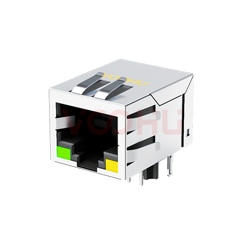
Read the PoE line as printed. The SYT411Q211DB2A1DP2 (2.5G) states a balanced DC line current of 720 mA maximum at 57 V DC continuous; the SYT4A11Q855HWA10DPB1359 (10G) states 1.5 A maximum at 57 V DC continuous. That figure is the DC current the center-tap windings of the magnetics are rated to carry, not a per-pin contact rating. Neither datasheet says whether it applies per pair or per port, so confirm the scope with our FAE team before you set a power budget, and compare it with the current your PSE or PD design actually draws.
A Wi-Fi 7 access point is a typical design that needs both multigig and PoE on one port; see Wi-Fi 7 AP uplink and PoE design. For matching jack current to the PoE type of your design, see PoE MagJack selection.
#Can a 2.5G MagJack replace a Gigabit MagJack on the same footprint?
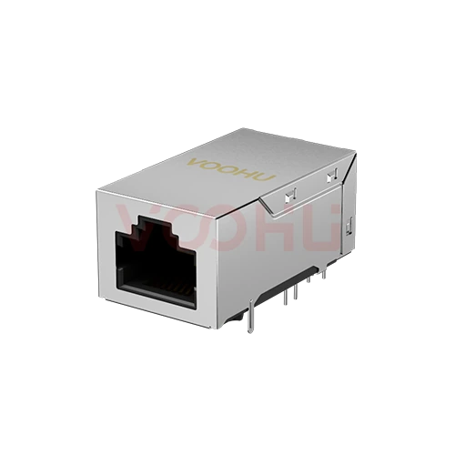
Only after you check: a direct swap has to be confirmed, not assumed. Compare the drawings line by line: pin numbering on the recommended PCB layout, hole sizes and positions, tab direction, LED pins and shield tabs. Then compare the schematics. On the SYT111Q652EA2A1D2, the PHY-side center taps are brought out together on pin 1, labelled VCC, with no separate center-tap pins. If your Gigabit layout has a center-tap pin per pair, or ties the center taps to a different rail, the PCB or the bias network changes. Your PHY datasheet tells you what the center taps need; the jack schematic tells you which pin carries them. For pin numbering, see the RJ45 jack pinout with integrated magnetics; send both part numbers and our FAE team can help check the swap.
#Ports, tab, LEDs and plating: what to fix before you ask for samples
Once the electrical lines fit, the remaining choices are mechanical, and they are the ones a buyer has to write into the request. Port count: the SYT112T010AB2A10DB is a 1×2 10G jack, two ports in one housing, while the other parts in the table are 1×1. Tab direction: tab up or tab down sets which way the latch faces on the panel. LEDs: decide the colors, or whether the port needs them at all. Plating: 6U" and 30U" gold both appear in the table; see RJ45 gold plating: 3U, 6U and 50U for how plating relates to mating cycles. All parts in the table are rated for −40 to +85 °C.
To see the full range, open the RJ45 selector with integrated magnetics and 2.5G, 5G and 10G Base-T already filtered, then narrow it by PoE, ports, tab and LEDs. You can also start from a single rate: 2.5G, 5G or 10G Base-T. Every row links to its datasheet.
#FAQ
Is 10GBASE-T copper or fiber?
10GBASE-T is copper: it runs over four twisted pairs through an RJ45 connector, as defined in IEEE 802.3 Clause 55. A 10G MagJack sits between the PHY and that cable. 10G over fiber uses different PHYs and optical modules, such as SFP+ transceivers, and does not use an RJ45 MagJack.
Is 2.5G Ethernet backwards compatible with 1G?
That is decided by the PHY, not the jack. A multigig PHY negotiates the link rate with the device at the other end, and the link only runs at 2.5G when both ends support 2.5GBASE-T. Check the PHY datasheet for the lower rates it supports, and choose the MagJack for the highest rate you plan to run.
What is magnetics in Ethernet?
Ethernet magnetics are the transformers and common mode chokes between the PHY and the RJ45 port. They isolate the board from the cable, pass the differential signal and suppress common-mode noise. In a MagJack they sit inside the jack; for the discrete version, see how to connect a LAN transformer to a PHY.
Can a non-PoE MagJack carry PoE?
Plan PoE only on a jack whose datasheet states a DC line current. The non-PoE parts in the table above have no such line, so their magnetics are not specified for it. If the port may gain PoE later, choose the PoE version now, and compare the drawings, because the footprint can differ.
Get multigig MagJack samples for your design
Send us your PHY, the highest link rate, port count, tab direction, LED colors and the PoE current you need through our sample request form. Our FAE team can suggest suitable parts and help check the design, from the loss lines against your PHY's requirements to the center-tap connection and the footprint of your current jack. Samples are available for evaluation, and selected parts are free of charge. Our FAE team will be glad to confirm the options for your project. VOOHU supplies RJ45 and SFP connectors, LAN and PoE transformers and common mode chokes from Suzhou, China, to more than 1,500 customers.
#Sources
- VOOHU SYT111Q652EA2A1D2 datasheet, Rev. A0
- VOOHU SYT111Q340AB2A1DB2 datasheet, Rev. A0
- VOOHU SYT411Q211DB2A1DP2 datasheet, Rev. A0
- VOOHU SYT111Q624AB2A12DB5 datasheet, Rev. A0
- VOOHU SYT112T010AB2A10DB datasheet, Rev. A0
- VOOHU SYT4A11Q855HWA10DPB1359 datasheet, Rev. A0
- VOOHU SYT411Q199DB2A1DP datasheet, Rev. A0
- IEEE 802.3-2022, Clause 126 (2.5GBASE-T and 5GBASE-T, from IEEE 802.3bz)
- IEEE 802.3-2022, Clause 55 (10GBASE-T, from IEEE 802.3an)
Need a quote, samples or selection support?
Part number SYT111Q652EA2A1D2 is filled in for you. Add the quantity and lead time and submit. Our FAE team will be glad to confirm the options for your project.
Before you order: samples, MOQ, lead time and import duties in our ordering guide →