An Ethernet port circuit is the short stretch of hardware between the RJ45 jack and the PHY chip. From the cable inward it has four parts: the RJ45, a LAN transformer, the termination and center-tap network, and the PHY, plus protection and grounding. Together they decide whether the link negotiates reliably and passes EMC and surge tests.
#Where the Ethernet Port Circuit Sits
Every networked device, from a router or switch to an IP camera or an industrial controller, has an RJ45 jack on its enclosure. Plug in a cable, the LEDs come on, and the link is up. Behind that jack, a small area of the board carries the signal to the chip that actually transmits and receives Ethernet data.
That chip is the PHY (Ethernet physical-layer transceiver). It drives differential signals on its MDI (media-dependent interface) pins. The Ethernet port circuit, also called the Ethernet interface circuit or PHY peripheral circuitry, runs from those MDI pins, through a LAN transformer (or an RJ45 with integrated magnetics, or a chip LAN), to the RJ45 cable contacts.
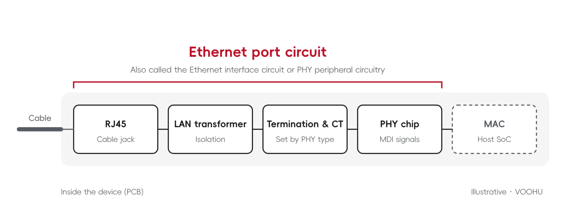
Figure 1. Where the Ethernet port circuit sits between the RJ45 and the PHY (illustrative)
Small as it is, this circuit has three jobs at once:
- pass the signal cleanly so the link negotiates and stays up;
- keep external noise and surges out, so the port passes EMC and surge tests;
- keep circuit ground (GND) separate from chassis ground (SHIELD) and define how the two relate.
When a port will not link, drops intermittently, falls back from Gigabit to 100 Mbps, or dies after a lightning or surge event, troubleshooting comes back to this circuit. Our article on what to check when an Ethernet port is dead after a surge walks through that diagnosis step by step.
#The Four Parts, from the RJ45 Inward
Follow the cable into the device and you meet four parts in order: the RJ45, the LAN transformer, the termination and center taps, and the PHY chip.
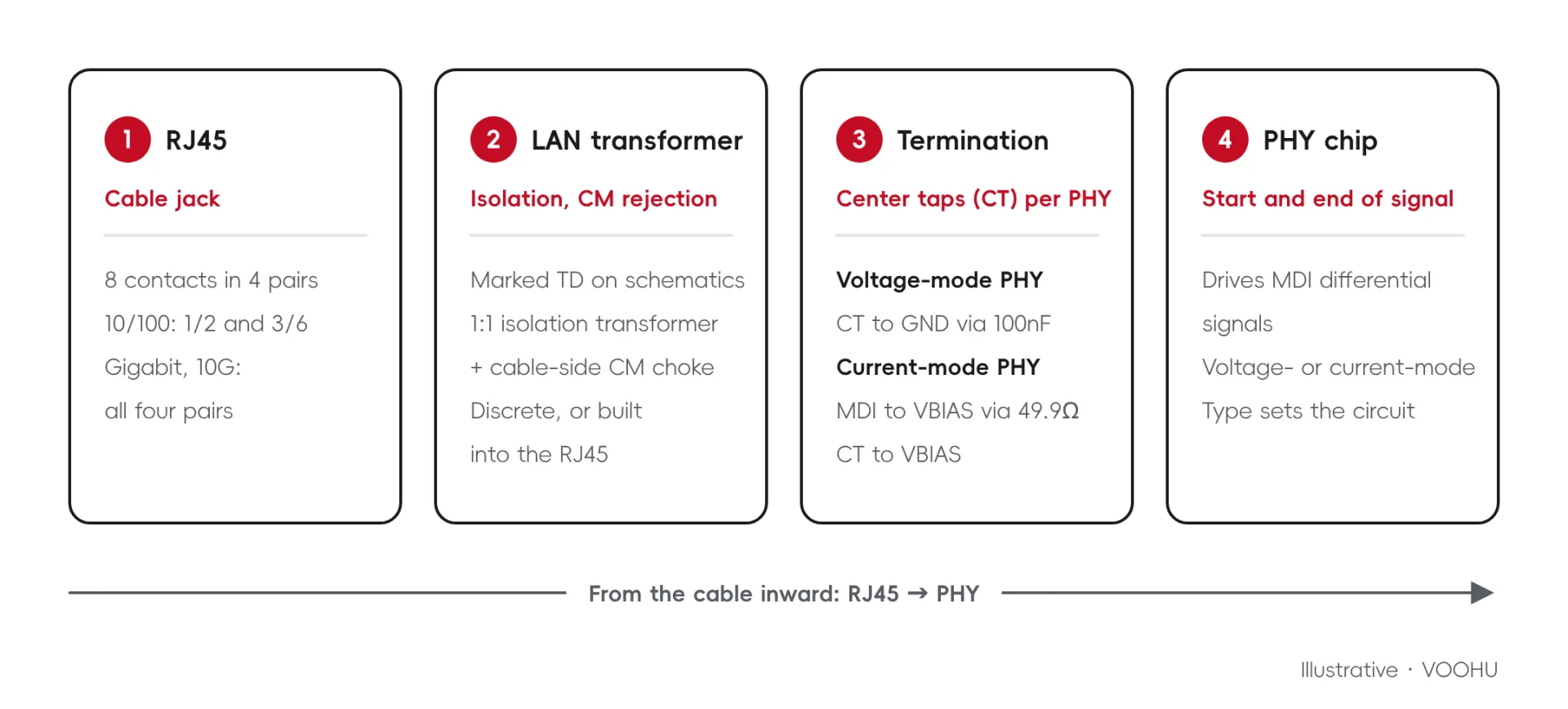
Figure 2. The four parts of an Ethernet port circuit (illustrative)
RJ45 connector: where the cable plugs in
The RJ45 connector is the only part of the circuit you can see from outside. Its eight contacts form four pairs that match the four twisted pairs in the cable. How many pairs carry data depends on speed. A 10/100 Mbps port uses two pairs, 1/2 and 3/6, and leaves 4/5 and 7/8 unused. Gigabit and 10G ports transmit and receive on all four pairs, connected in order to 1/2, 3/6, 4/5 and 7/8.
LAN transformer: isolation and common-mode rejection
Right behind the RJ45 there is usually a LAN transformer, marked TD on many schematics. Inside it is a 1:1 isolation transformer plus a cable-side common-mode choke, and it does two things:
- Galvanic isolation: there is no direct conductive path between the device side and the cable side; the signal crosses magnetically.
- Common-mode rejection: the choke blocks noise that appears in phase on both wires of a pair, while the differential signal passes.
On the board it is the black SMD or through-hole part with closely spaced pins next to the jack. It can be a discrete part, or it can be built into the RJ45. For how its internal channels and ports are organized, see How to Choose a LAN Transformer (Part 1).
Termination and center taps: wired to suit the PHY
Each winding of the transformer brings out a center tap (CT). On the PHY side, how the center taps and MDI lines are wired depends on the type of PHY:
- Voltage-mode PHY: termination is on-chip, so there are no external 49.9Ω resistors on the MDI lines, and each center tap goes to ground through a 100nF capacitor.
- Current-mode PHY: each MDI line connects to the bias supply VBIAS through 49.9Ω, and the center taps also connect to VBIAS.
The two circuits cannot be mixed; follow the vendor documentation for the selected PHY, and place each bypass capacitor close to its pin. Voltage-Mode vs Current-Mode Ethernet PHY explains the drive mechanisms and peripheral design in more depth.
PHY chip: where the signal starts and ends
The Ethernet PHY turns data into the differential signals on the cable and recovers received signals back into data. Whether it is voltage-mode or current-mode determines how everything in front of it is wired, so the design of the whole port circuit starts with the choice of PHY. Each VOOHU reference design states the PHY architecture it applies to in its Scope section.
#Protection and Grounding
Alongside the signal path, part of the port circuit works where you cannot see it: protection and grounding.
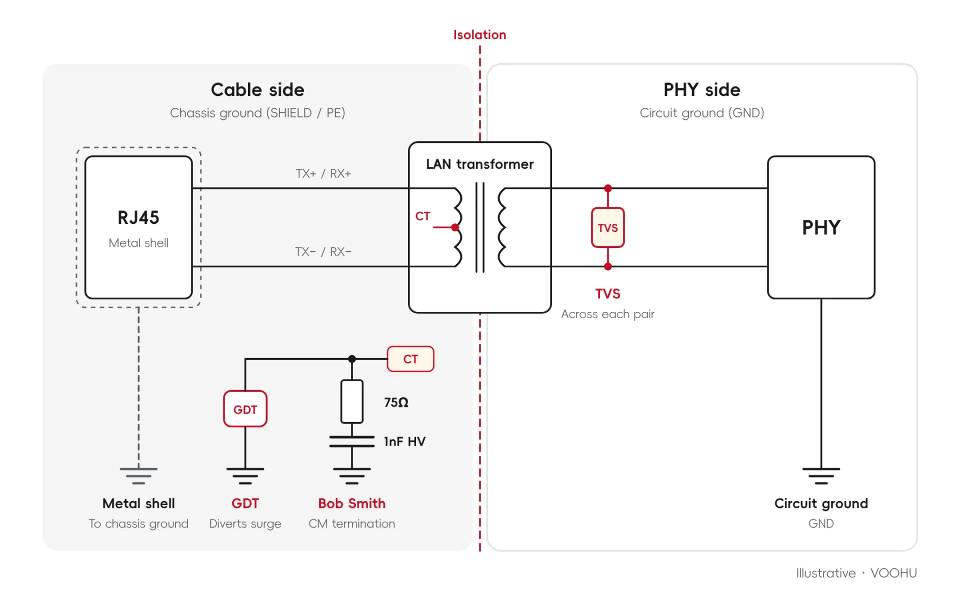
Figure 3. Protection and grounding in an Ethernet port (illustrative; one pair shown)
- Bob Smith termination: the cable-side center taps (plus the unused pairs on 10/100 Mbps) each connect through 75Ω to one common point, which connects to chassis ground through a 1nF high-voltage capacitor. It is common-mode termination only and does not replace surge protection.
- TVS: placed on the PHY side to limit the transients that reach the PHY. In designs with a LAN transformer it is connected across each pair; in capacitively coupled designs it is connected from each line to ground. See VOOHU TVS diodes and ESD protection devices.
- GDT (gas discharge tube): connected between the cable-side center taps and chassis ground (PE) to divert surge current. Select it together with the TVS and the magnetics.
- Chassis ground and circuit ground: the RJ45 metal shell connects to chassis ground (SHIELD), and circuit ground (GND) is a separate net. How the two connect is part of the system design.
Each of these parts guards one stage. For staged protection, compare the surge and ESD reference designs for 10/100BASE-TX, 1000BASE-T and 10GBASE-T ports.
#Three Ways to Build the Same Port
Combining these parts gives three common ways to build an Ethernet port circuit.
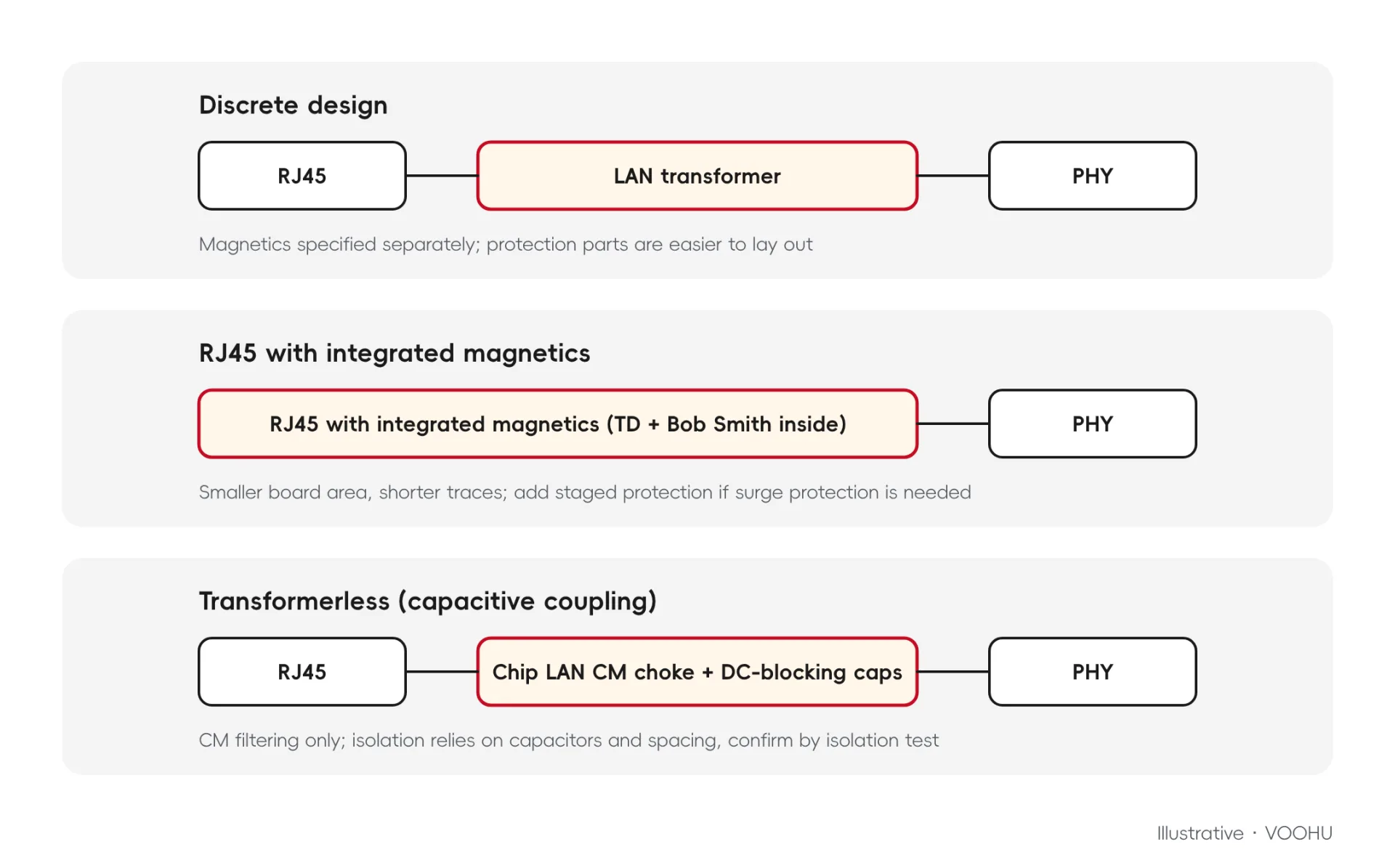
Figure 4. Three ways to build an Ethernet port circuit (illustrative)
- Discrete design: a discrete RJ45 plus an external LAN transformer. The magnetics can be specified separately, and protection devices are easier to lay out. Reference: 10/100BASE-TX discrete RJ45 + external LAN transformer.
- RJ45 with integrated magnetics: the LAN transformer and the Bob Smith termination sit inside the RJ45. Board area is smaller and traces are shorter; if the port needs surge protection, add staged protection around it. From the outside, there is no separate transformer behind the jack. Reference: Gigabit RJ45 with integrated magnetics.
- Transformerless (capacitive coupling): no LAN transformer. DC-blocking capacitors work with a chip LAN common-mode choke for common-mode filtering only; isolation relies on the capacitors and spacing and must be confirmed by port isolation testing. If the goal is a standard 100 m Ethernet port, the reference design recommends a magnetically isolated architecture with validation evidence, that is, a design with a LAN transformer. Reference: 10/100BASE-TX capacitive coupling.
Which one fits depends on the PHY type, the data rate and the board space available.
#What Changes Between 10/100, Gigabit and 10G
The backbone of the port circuit is the same at every speed. Two things change:
- Pairs in use: 10/100 Mbps uses two pairs; Gigabit and 10G use all four.
- Channels in the LAN transformer: one differential pair is one channel, so 10/100 Mbps needs 2 channels, and Gigabit and above need 4.
The VOOHU reference designs are grouped the same way: three for 10/100 Mbps, two for Gigabit and two for 10G, plus one surge and ESD protection design each for 10/100 Mbps and Gigabit ports.
#Quick Reference: The Parts at a Glance
#FAQ
What are the parts of an Ethernet port circuit?
From the RJ45 inward: the RJ45 connector, the LAN transformer, the termination and center-tap network, and the PHY chip. Protection parts (Bob Smith termination, TVS, GDT) and the split between chassis ground and circuit ground complete the circuit.
Does every Ethernet port need a LAN transformer?
No. A transformerless design uses DC-blocking capacitors with a chip LAN common-mode choke, and its isolation must be confirmed by port isolation testing. For a standard 100 m port, the reference design recommends a magnetically isolated design with a LAN transformer.
Can Bob Smith termination replace surge protection?
No. Bob Smith termination ties the cable-side center taps through 75Ω resistors and a 1nF high-voltage capacitor to chassis ground for common-mode termination only. Surge protection comes from the GDT on the cable side and the TVS on the PHY side, selected together with the magnetics.
How does a 10/100 port circuit differ from a Gigabit one?
A 10/100 port uses pairs 1/2 and 3/6 and a 2-channel LAN transformer; a Gigabit port uses all four pairs and a 4-channel transformer. In both cases the termination is wired according to whether the PHY is voltage-mode or current-mode.
#Reference Designs and VOOHU Parts
The VOOHU solution center collects nine Ethernet port reference designs covering 10/100, Gigabit and 10G, each with a schematic, design notes, related parts and a PDF download. In the 10/100 discrete design, a SYT561188-AB1A3DY1027 RJ45 jack without magnetics pairs with a WHS16013LF 10/100BASE-TX LAN transformer. For a Gigabit port with integrated magnetics, the SYT-320DNL RJ45 with integrated magnetics is an option. Final part numbers must be checked against the PHY vendor documentation and the circuit parameters.
Browse all nine designs in Ethernet PHY Reference Designs: 10/100, Gigabit and 10G Port Schematics, read Ethernet Circuit Design: How Do You Connect the PHY, Magnetics and RJ45?, or contact a VOOHU FAE with your PHY part number for a selection check.
Need a quote, samples or selection support?
Part number SYT561188AB1A3DY1027 is filled in for you. Add the quantity and lead time and submit. Our FAE team will be glad to confirm the options for your project.
Before you order: samples, MOQ, lead time and import duties in our ordering guide →