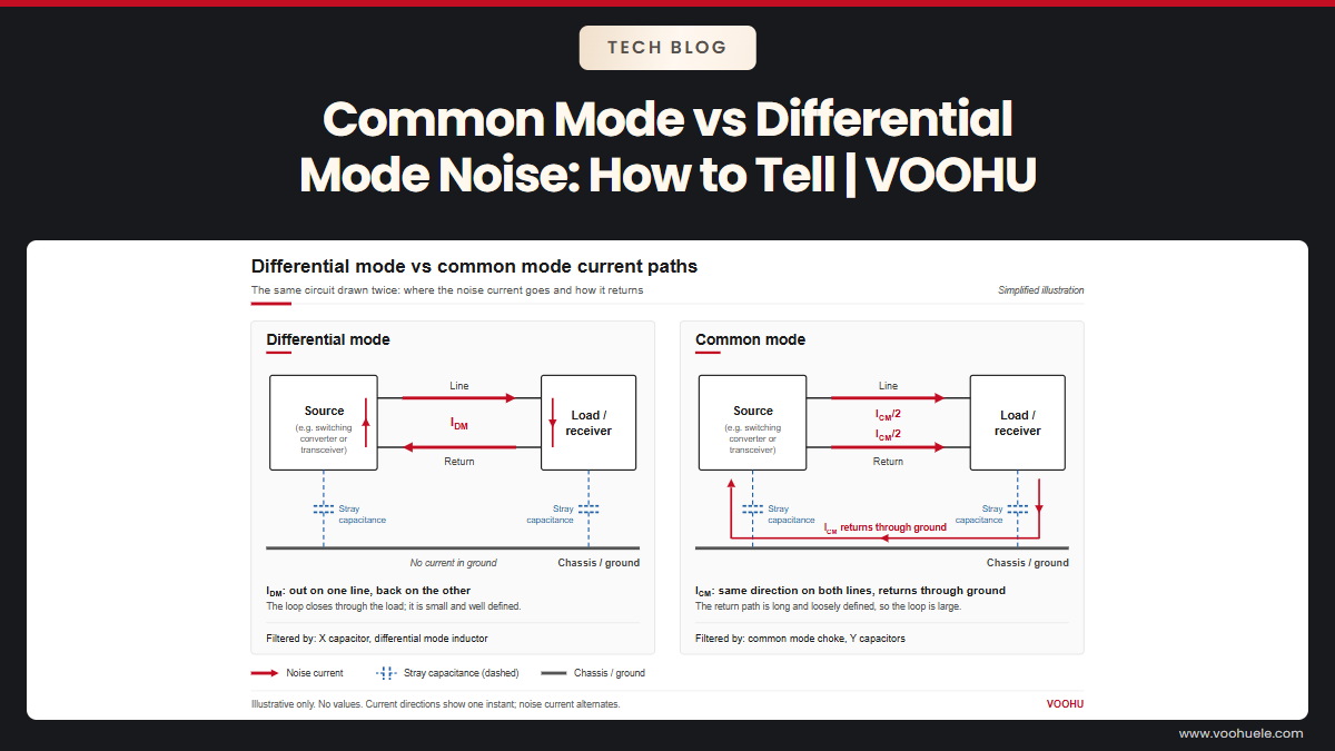
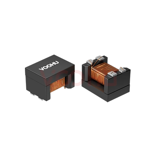
A CAN bus common mode choke is optional. Many CAN transceivers are designed to meet EMC requirements without one, so fit a choke when a node with a clean layout and split termination still fails emissions or immunity tests, or when the cable runs past motors and drives. Choose it on four points: common mode impedance at the frequency of your noise, read at the datasheet's stated test frequency; low leakage inductance and DCR, so CAN FD edges stay clean; the flyback transient it creates when a bus line is shorted, measured on your node; and a TVS on the transceiver side of the choke. VOOHU's WHAC-3225B-U0 and WHAC-4532A-U0 datasheets list CAN FD and CAN bus lines, with 11 µH to 100 µH options and common mode impedance specified at 10 MHz, and our FAE team can help you pick the steps to compare.
#Is a common mode choke necessary for a CAN transceiver?
Not by default. TI's application report SLLA271, Common Mode Chokes in CAN Networks, notes that many modern CAN transceivers are optimized for EMC and a wide common-mode range so they can work without a choke, and that chokes are sometimes added "out of perceived need". Engineers ask the same about the TCAN1044 and TCAN1043 on TI's forum. Fit a choke when you can point to the problem it solves:
- Radiated emissions from the cable that remain after layout and termination are right.
- Immunity failures where the disturbance arrives in common mode on CAN_H and CAN_L.
- Long unshielded runs near motors, drives or lighting. TI's SLLA270, Controller Area Network Physical Layer Requirements, notes that induced voltages of 10 V or more are commonly found on industrial buses.
Check the cheaper fixes first: split termination at the two bus ends, with matched resistors and a capacitor to ground, and the transceiver's SPLIT or VREF pin if it has one, which TI says stabilizes the common-mode bus voltage and helps reduce radiated emissions. Then measure the common mode current on the cable with a current probe, once with the choke fitted and once with its footprint bridged by a 0 Ω link. A ferrite bead on each line is not a substitute: it attenuates the CAN signal along with the noise.
#What can a common mode choke do wrong on a CAN bus?
The inductance that blocks common mode noise also stores energy. SLLA271 looks at a CAN line shorted to a DC voltage: as the transceiver switches between dominant and recessive, the change in current through the choke can fly back to more than 65 V, while a typical transceiver's maximum operating range is about −27 V to 40 V. TI also reports:
- The transient depends on the choke's winding type, core type and inductance, and on termination, cabling and the short itself, so two chokes with the same inductance can behave differently.
- TVS capacitance can ring with the choke's inductance; TI notes the ringing does not corrupt CAN signals but may show up as higher-frequency emissions.
- Immunity can get worse in some frequency ranges, and signal integrity can degrade.
#Where do the TVS, common mode choke and split termination go?
The order on a terminating node, following TI's SLLA271 workaround, is shown below, followed by the reasons for each position. For the rest of the node, from transceiver choice to isolation, see our guide to CAN bus communication circuit design and the CAN bus solution page.
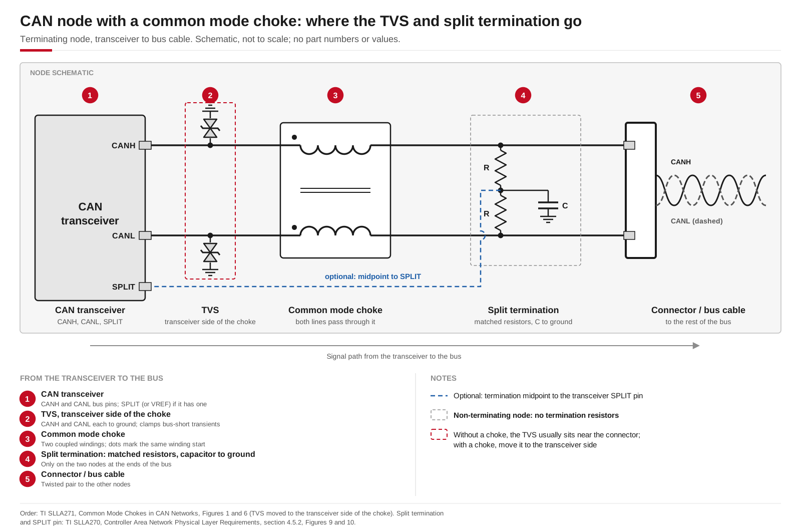
Placement on a terminating CAN node with a common mode choke, following TI SLLA271 and SLLA270. A non-terminating node has no termination resistors. Schematic, not to scale.
Common mode choke. In TI's example node, the choke sits between the transceiver and the termination circuit, so both bus lines pass through it before they reach the termination and the cable. Route CAN_H and CAN_L symmetrically through it, with the same width, spacing, layer and via count.
TVS. Without a choke, the TVS usually sits close to the connector. With a choke, the high transients from a bus short appear between the choke and the transceiver, so SLLA271 moves the transient protectors to the transceiver side of the choke, where they clamp before the bus pins. Pick a fast TVS with low capacitance, because of the ringing described above.
Split termination. TI's SLLA270 describes split termination as two matched resistors of about 60 Ω each, with a capacitor from their midpoint to ground; the resistors must be matched carefully, or the immunity it adds is reduced. It belongs only on the two nodes at the physical ends of the bus, while a choke can sit on any node. The capacitor value depends on the signalling rate, so take it from your transceiver datasheet.
#Common mode choke for CAN FD: what changes?
CAN FD keeps the arbitration phase at up to 1 Mbit/s and switches to a higher bit rate for the data phase; CAN in Automation (CiA) notes that the data-phase rate is limited by the transceiver characteristics. Shorter bits leave less time for edges to settle before the sample point, so leakage inductance, the ringing it forms with TVS and bus capacitance, imbalance between the windings and DCR in series with the bus all start to count. Common mode impedance alone tells you none of this, so check the choke at your real data-phase rate:
- 1.Fix the data-phase bit rate, sample point and worst-case topology you will really run.
- 2.Build the node with the choke bridged and with two or three candidate inductance steps, on the same board and cable.
- 3.At a receiving node, capture CAN_H, CAN_L and the differential voltage; check ringing around the sample point and the error counters under bus load.
- 4.Short CAN_H, then CAN_L, to your supply voltage while the node transmits, and measure the transceiver bus pins, as SLLA271 does.
- 5.Repeat the emissions and immunity scans and keep the lowest step that passes. To check a VOOHU part against your data-phase rate first, ask our FAE team.
You may also meet IEC 62228-3 in test plans. According to the IEC publication page, it specifies methods for EMC evaluation of CAN transceiver ICs under network conditions, and the 2019 edition, which replaced IEC TS 62228, added flexible data rate transceivers and an annex on common mode choke characterization. It evaluates transceivers; your module still needs its own system-level EMC tests.
#CAN common mode choke selection: comparing VOOHU 3225 and 4532 parts
The two VOOHU signal line common mode chokes series below are the ones whose datasheets list CAN FD, CAN bus, A2B and other high-speed differential signal lines, including PLC data lines. Each series has four inductance steps. Every impedance in the table is common mode impedance at 10 MHz, the test frequency these datasheets use, so do not compare it directly with figures quoted at 100 MHz.
How to read the table:
- Common mode impedance rises with inductance, from 550 Ω typical at 11 µH to 5,100 Ω at 100 µH in the 3225 series, but leakage inductance (50 to 180 nH) and DCR (0.8 to 4.9 Ω) rise with it. The largest value is not automatically the right one for a CAN FD node.
- At the same inductance, the 4532 parts give a slightly higher typical impedance, and at 100 µH a lower DCR. The 4532 size is 4.50 × 3.20 mm, 2.30 mm high; choose 3225 where board area is tight.
Both series give an operating temperature of −55 °C to +150 °C per the datasheet, and an inductance tolerance of +50/−30%, so leave margin if your filter design depends on a particular value.
For a first A/B comparison, a practical pair in the 3225 size is WHAC-3225B-220U0 (22 µH) and WHAC-3225B-510U0 (51 µH). If you have the room and need more common mode impedance, compare WHAC-4532A-510U0 (51 µH) with WHAC-4532A-101U0 (100 µH). You can browse all 3225 signal line chokes and 4532 signal line chokes in the selector. For in-vehicle projects, ask our FAE team which documents apply before you design the part in.
#What to check before a CAN choke goes into the BOM
- Compare common mode impedance only at the same test frequency (10 MHz for the parts above), and note whether a figure is minimum or typical.
- Compare leakage inductance and DCR too; a second source with the same inductance can ring differently on a CAN FD bus.
- Repeat the bus short-circuit check with the TVS fitted for any substitute, since the transient depends on winding and core type as well as inductance.
- Use the land pattern, pin assignment and orientation marking from the choke's own datasheet; 3225 and 4532 parts need different footprints.
#FAQ
Does a low-speed CAN bus need a common mode choke?
Use the same test as at any rate: fit one only if a measured common mode problem needs it. At lower bit rates, edges have more time to settle, so the choke's effect on the differential signal is less critical. The flyback transient during a bus short occurs at any bit rate, so TVS placement and the short-circuit check still apply.
Should the TVS go before or after the common mode choke on a CAN bus?
When a choke is fitted, put the TVS on the transceiver side of it. TI's SLLA271 shows that the high transients from a bus short appear between the choke and the transceiver, so clamping there protects the bus pins. Keep the TVS capacitance low to avoid ringing with the choke.
Does a common mode choke protect a CAN node against ESD, load dumps and ground shifts?
Not on its own. ESD and fast transients on CAN_H and CAN_L are the TVS's job, a load dump on the supply is handled in the power input circuit, and ground shift is handled by the transceiver's common-mode range (TI cites −2 V to 7 V for ISO 11898) or by isolation. See CAN bus communication circuit design for the full protection chain.
Which VOOHU common mode chokes list CAN FD in their datasheets?
The WHAC-3225B-U0 and WHAC-4532A-U0 series, eight parts from 11 µH to 100 µH, such as WHAC-3225B-510U0 (51 µH, 2,600 Ω typical at 10 MHz). Send us your transceiver and data-phase rate, and our FAE team will confirm the part for your node.
Get samples to compare on your CAN node
Working on a CAN or CAN FD node that fails emissions or immunity, or deciding whether to keep a choke footprint? Send us your transceiver, data-phase bit rate, cable length and whether the node terminates the bus through our sample and support form. Our FAE team can suggest the inductance steps to compare and help check the TVS, choke and termination placement on your layout. Samples are available for evaluation, and selected parts are free of charge. Our FAE team will be glad to confirm the options for your project. VOOHU supplies RJ45 and SFP connectors, LAN and PoE transformers and common mode chokes from Suzhou, China, to more than 1,500 customers.
Need a quote, samples or selection support?
Part number WHAC3225B510U0 is filled in for you. Add the quantity and lead time and submit. Our FAE team will be glad to confirm the options for your project.
Before you order: samples, MOQ, lead time and import duties in our ordering guide →