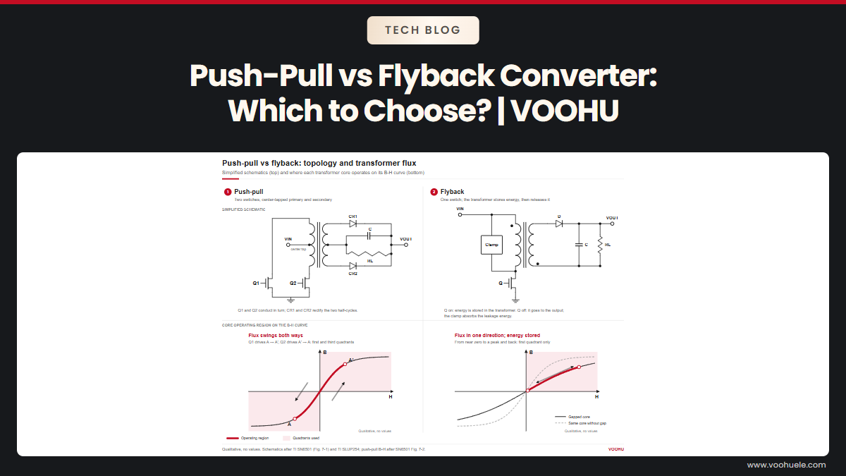
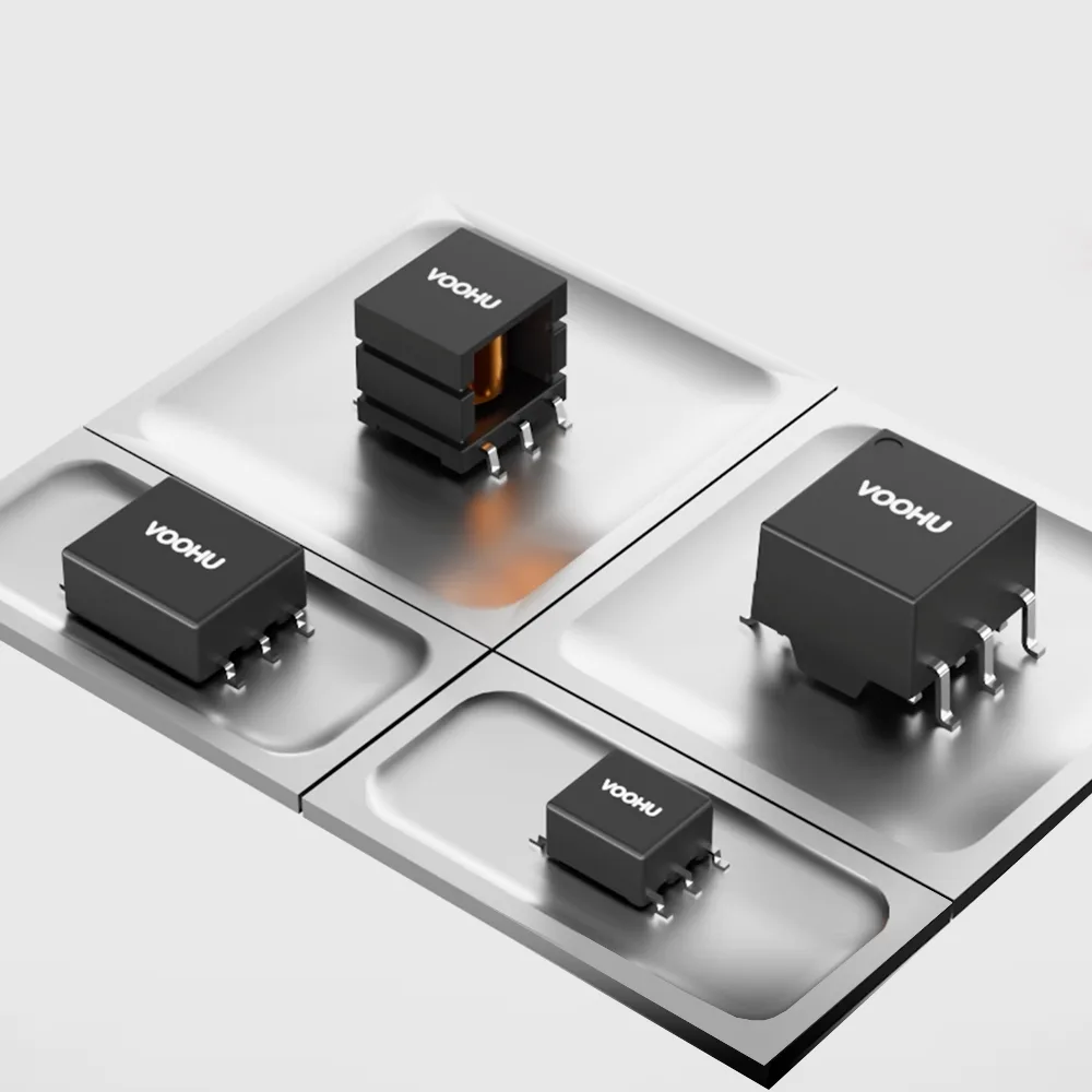
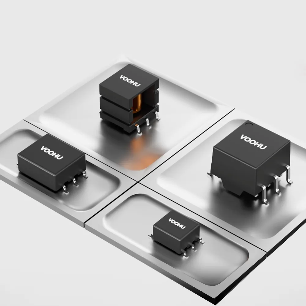
The Texas Instruments SN6501 and SN6505 are transformer drivers, not transformers: they switch the two ends of a center-tapped primary, and the transformer you add decides the output voltage, the isolation and whether the core stays out of saturation. Choose an SN6501 or SN6505 transformer in three steps. First, take the lowest switching frequency from the TI datasheet and work out the minimum volt-time (V·t) product. Second, set the turns ratio from your input, output and regulator dropout. Third, match the isolation rating to your interface. The driver variant matters, because the SN6501, SN6505A and SN6505B switch at different frequencies. VOOHU offers center-tapped push-pull transformers with 1CT:1.1CT and 1CT:2.88CT ratios, and parts with isolation ratings up to 4 kVrms; our FAE team can check the fit for your driver.
#Is the SN6501 a transformer driver or a transformer?
It is a driver. The SN6501 datasheet describes a push-pull driver for small transformers that runs from 3.3 V or 5 V and drives the primary with up to 350 mA at 5 V and 150 mA at 3.3 V, using two complementary outputs with a 50% duty cycle and break-before-make timing. The SN6505 datasheet covers a 1 A version for 2.25 V to 5.5 V that adds spread-spectrum clocking, a 1.7 A current limit, soft-start and thermal shutdown. Either way you still need a center-tapped transformer, rectifier diodes and usually an LDO. For the general operating principle, see push-pull converter working principle.
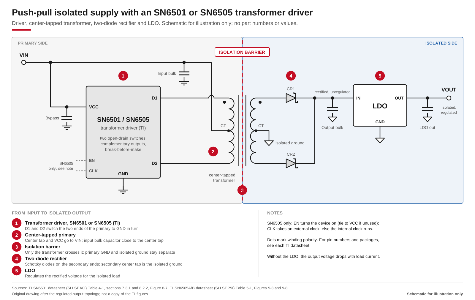
Typical push-pull isolated supply: the driver switches each end of the center-tapped primary, the secondary is rectified and an LDO regulates the output. Drawn after the regulated-output topology in the TI SN6501 and SN6505 datasheets; schematic for illustration only.
#How do you work out the volt-time product the transformer needs?
The volt-time product is what keeps the core out of saturation. TI's method is to take the highest voltage the driver puts across the primary, which is the nominal supply plus 10%, and the longest time it stays there, which is half the period at the lowest switching frequency in the datasheet. The transformer's V·t rating must be greater than VIN-max / (2 × fmin). Because the SN6501, SN6505A and SN6505B switch at different frequencies, the same 5 V rail gives quite different minimums:
Source: TI SN6501 datasheet (SLLSEA0I), electrical characteristics and section 8.2.2.5.1; TI SN6505A/B datasheet (SLLSEP9I), electrical characteristics and section 9.2.2.5.1.
Use the minimum frequency, not the typical one: the core sees the longest half-period at the low end of the range. If you clock an SN6505 from its CLK pin, repeat the calculation with your own lowest clock frequency. V·t is only one check; TI notes that isolation voltage, power rating and turns ratio still decide the final part.
VOOHU datasheets print this rating in their own words: "Voltage-Time: 15Vus" on the WHST06Q02E0, a "V-µsec" column of 24 or 27 Max across pins 1-3 on the WHST060xxA0 series, depending on the part, and "V-µsec(1-3): 20 Max" on the WHST06032G0.
Do not set these numbers next to TI's minimums and read off a pass or fail. TI's minimum is the supply voltage applied to the primary for half a switching period; the VOOHU datasheets do not state which part of the switching cycle their figure refers to, so the two are not yet the same quantity. Send us the driver, the supply voltage and the lowest switching frequency in your design, and our FAE team will confirm the volt-time margin for the part. For what happens when the two half-cycles are unequal, see push-pull transformer flux bias.
#What turns ratio do I need for a 3.3 V or 5 V input?
With an LDO after the rectifier, TI's starting points are about 1.5 (±3%) for 3.3 V to 3.3 V and for 5 V to 5 V, and 2.2 (±3%) for 3.3 V to 5 V. For your own parts, TI gives nmin = 1.031 × (VF-max + VDO-max + VO-max) / (VIN-min − RDS-max × ID-max): diode drop, LDO dropout and output on top, the primary voltage left after the driver's switch drop below, and 1.031 for a typical 97% transformer efficiency. Also check the no-load end: the secondary rises to VIN-max × n, and the LDO's maximum input must be higher than that. Without an LDO, TI uses 1:1.1 and 1:1.7 ratios for low-current logic rails. The magnetic design behind these ratios is covered in the push-pull transformer design guide.
#SN6501 vs SN6505: can the SN6501 be replaced with the SN6505B without changing the transformer?
Often the volt-time side is not the problem, but recheck the transformer before you swap the driver:
- Frequency and V·t. At 5 V, TI's example minimum is 7.6 V·µs for the SN6505B against 9.1 V·µs for the SN6501. The SN6505A is different: its example minimum is 20 V·µs, so confirm the transformer's rating again.
- Current. The SN6505 drives 1 A at 5 V, against 350 mA for the SN6501. If you swap for more output power, check the transformer's winding resistance and power rating; the 1.7 A current limit in the SN6505 datasheet protects the driver, not the transformer.
- Turns ratio. The SN6505's lower switch resistance changes the primary voltage in the nmin formula above, so recalculate the full-load output and the no-load voltage at the LDO input.
If your transformer is a VOOHU part, send both driver part numbers and your load, and our FAE team will check it against the new driver.
#How do you derive +12 V or +15 V for a gate driver from an SN6501?
Isolated gate-driver bias is a common reason to look beyond 1:1.1 parts. TI states that both drivers can supply outputs up to 30 V, or bipolar outputs up to ±15 V, by pairing center-tapped transformers with turns ratios of 0.8 to 5 with different rectifiers, such as a bridge on a center-tapped secondary or a voltage doubler. A higher step-up ratio raises the primary current for the same output power, so keep it inside the driver's limit before you settle on the ratio.
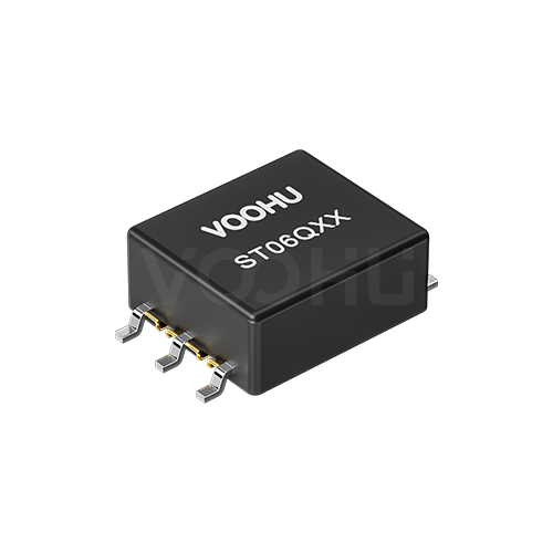
For a 12 V rail from 5 V, the VOOHU WHST06Q02E0 is a useful reference: it has a 1CT:2.88CT ±3% ratio, and its datasheet includes a typical application of 5 V in, 12 V out at 460 mA with a 400 kHz switching frequency. The datasheet notes that values may vary by application, so treat this as the operating point the part is documented around, not as a rating for any particular driver.
#Which VOOHU push-pull transformer should you start from?
The table lists what each VOOHU datasheet states. Inductance is shown with its own test condition, because the parts are measured differently and the values cannot be compared as one range.
How to use the table:
- 3.3 V to 3.3 V or 5 V to 5 V logic rails: start from WHST06E14A1, whose 1CT:1.1CT ratio matches the ratio TI uses for logic rails without an LDO; ask our FAE for its volt-time rating at your frequency.
- 12 V bias from 5 V: start from WHST06Q02E0 and its documented 400 kHz operating point.
- Higher isolation: the WHST060xxA0 series lists 4 kVrms, and WHST06032G0 lists a 4000 Vrms hipot with 8 mm creepage and clearance. Their datasheets describe a gate-drive application, so confirm with our FAE that the winding arrangement suits your push-pull stage.
VOOHU's product catalog groups the WHST060, WHST06D and WHST06E series under isolated interface power supplies for CAN. To compare every series, open the push-pull transformer selector and switch the series filter. Part-level comparison reports are available for WHST06Q02E0 and WHST06E14A1.
#FAQ
Why does my SN6501 not drive the transformer?
Start with the limits in the TI datasheet. The SN6501 has no soft-start, current limit or thermal shutdown, and TI warns that more than 5 µF of load capacitance looks like a short circuit to it at power-up. Then check that the primary current stays within 350 mA at 5 V or 150 mA at 3.3 V, that the primary center tap goes to VCC with D1 and D2 on the two ends, and that the transformer's volt-time rating covers the minimum for your supply.
Can I use the same transformer with the SN6501 and the SN6505?
Sometimes, but check it rather than assume it. With the SN6505B, the volt-time requirement in TI's 5 V example is lower than with the SN6501, while the SN6505A needs 20 V·µs. The SN6505 can also drive up to 1 A, so the transformer may carry a higher primary current. Recalculate the turns ratio with the new driver's switch resistance as well.
What is the difference between the SN6505A and SN6505B for transformer selection?
The switching frequency. TI specifies a 160 kHz internal oscillator for the SN6505A, aimed at applications that need to minimize emissions, and 420 kHz for the SN6505B, aimed at higher efficiency and a smaller transformer. The lower frequency of the SN6505A means a longer half-period, so its minimum volt-time product in TI's 5 V example is 20 V·µs against 7.6 V·µs for the SN6505B.
Which transformer should I use with the SN6505 for a 5 V to 5 V isolated supply?
With an LDO on the output, TI's starting point for 5 V to 5 V is a turns ratio of about 1.5 (±3%); without an LDO, for a low-current logic rail, TI uses 1:1.1. In the VOOHU range, WHST06E14A1 has a 1CT:1.1CT ratio and a 3000 VAC, 2 s isolation test. Send us your SN6505 variant and load current, and our FAE team will confirm it or suggest another part.
Request push-pull transformer samples for your SN6501 or SN6505 design
Send us the driver part number, your supply and output voltages, the load current, the lowest switching frequency and the isolation your interface needs through our sample request form, and name a part from the table if you have one in mind. Our FAE team can suggest the turns ratio and part number and check the volt-time margin against your driver. Samples are available for evaluation, and selected parts are free of charge. Our FAE team will be glad to confirm the options for your project. VOOHU supplies RJ45 and SFP connectors, LAN and PoE transformers and common mode chokes from Suzhou, China, to more than 1,500 customers.
Need a quote, samples or selection support?
Part number WHST06Q02E0 is filled in for you. Add the quantity and lead time and submit. Our FAE team will be glad to confirm the options for your project.
Before you order: samples, MOQ, lead time and import duties in our ordering guide →