On an LP1188NL board, the questions this swap raises are mostly about space. The VOOHU WHS16037TG is a functional alternative to the LINK-PP LP1188NL — verify with samples in your design. Both are 16-pin SMD single-port 10/100 LAN transformers with 1CT:1CT windings, a common mode choke on the line side, 350 µH minimum OCL at 8 mA DC bias, 1500 V isolation and a −40 to +85 °C operating range, and each pin shown on the two schematics carries the corresponding function. The LP1188NL is drawn 5.10 mm tall and the WHS16037TG 5.65 ± 0.50 mm, both from the seating plane to the top of the body. The recommended pad rows also sit a little further out on the VOOHU drawing: 10.50 / 7.10 mm outer / inner, against 10.20 / 6.86 mm.
#LP1188NL vs. WHS16037TG: the two drawings, line by line
The LINK-PP column is read from the LP1188NL drawing LP10011954, revision A, dated 19 January 2010: sheet 1 holds the schematic and electrical table, sheet 2 the outline and suggested pad layout. Every LINK-PP figure here is a printed dimension; nothing is scaled off the drawing views. The VOOHU column comes from the WHS16037TG datasheet, revision A0: page 1 holds the outline, recommended pads and schematic, page 2 the electrical table. Where LINK-PP prints a dimension without a tolerance of its own, the drawing's general note of ±0.25 mm applies, and any range built from that note is marked as calculated. Lines marked "not stated" have no value on that sheet.
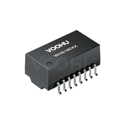
#LP1188NL height against the WHS16037TG: is there room above the part?
Start with what the two height figures measure, because a comparison only holds if both describe one dimension. They do here. Each drawing runs its height line from the seating plane, the line through the bottom of the leads, to the top of the body, so the 0.25 mm typical standoff is inside both numbers. LINK-PP prints 5.10 mm with no tolerance beside it; under the drawing's general ±0.25 mm note that is 4.85 to 5.35 mm. VOOHU prints 5.65 ± 0.50 mm, which is 5.15 to 6.15 mm (both ranges calculated). The nominal gap is 0.55 mm. Because the two ranges overlap, that does not mean every WHS16037TG stands 0.55 mm above every LP1188NL. The fair statement is about the upper limits: the tallest part either drawing allows is 5.35 mm for LINK-PP and 6.15 mm for VOOHU, up to 0.80 mm apart (calculated).
If you own the mechanics, 6.15 mm is the number to design against. Look at everything that sits directly over the transformer footprint: a board-level shield can sized around the LP1188NL, a rib, boss or label recess on the enclosure lid, a light pipe crossing the board, a daughter board or mezzanine on standoffs, a heat spreader. Measure the real gap from the PCB surface to the lowest of them, on the board or in the 3D assembly, and compare it with 6.15 mm plus whatever margin your mechanical rules require. A gap above that closes the question. A gap between 5.65 and 6.15 mm is the case to treat with care: measure the height of the samples you receive, and ask us about the spread before you commit the change.
Then fix the library, so the next clearance check runs on the right figure. Set the component height to 5.65 mm nominal and the 3D body or height keep-out to 6.15 mm. If an enclosure supplier works from your exported model, send the updated model rather than a note in an e-mail; a height field left at 5.10 mm is how this difference resurfaces on the next board revision.
#LP1188NL footprint: where the WHS16037TG pads sit
Along each row, the two land patterns agree: 0.76 mm wide pads on a 1.27 mm pitch, 8.89 mm from pin 1 to pin 8. Across the rows they part. LINK-PP suggests 10.20 mm between the outer edges and 6.86 mm between the inner edges; VOOHU recommends 10.50 mm and 7.10 mm, both typical. Centred on the part, each VOOHU pad starts about 0.12 mm further out at its inner end and finishes about 0.15 mm further out at its outer end (calculated). Neither drawing dimensions pad length directly, so no length is quoted here. The leads differ too: the foot that rests on the pad is 0.90 mm typical on the LP1188NL and 0.70 ± 0.15 mm on the WHS16037TG, while the width across the lead tips is 9.30 mm on both drawings.
For the Layout engineer with LINK-PP pads already on a board, those are fractions of a millimetre per side, and the real question is whether the WHS16037TG forms good heel and toe joints on copper drawn for a different lead. The drawings cannot settle that, and we have no written FAE confirmation for this pairing, so let the existing board answer it. Solder a handful of samples on it in a normal build, then look at the heel and toe fillets on the corner pins and on a couple in the middle of each row against your workmanship standard. If they pass, the current pads can carry the evaluation units. For a new layout, or a revision you are making anyway, draw the pads from the VOOHU drawing, and re-teach the AOI program for the shorter foot.
#Reading the LP1188NL electrical table beside the WHS16037TG
For the component engineer, most of the electrical table lines up without comment: OCL conditions, the −1.1 dB insertion loss ceiling, the 1500 V isolation voltage and the temperature range. Two notes belong in your evaluation sheet. First, LINK-PP heads its return loss, crosstalk and common mode rejection columns "dB TYP", while VOOHU states all three as minimums. A typical figure tells you how a middle-of-the-run part behaves; a minimum is the limit the datasheet sets for every part. Keep them in separate columns, as the table above does, and judge the VOOHU minimums against your PHY reference design or product requirement rather than against the LINK-PP typicals. If your form also has an insertion loss line between 0.1 and 1 MHz, the VOOHU sheet starts at 1 MHz, so ask us for data there. Second, isolation: both drawings state 1500 V, but only the VOOHU sheet gives the test terms, 1 mA for 60 s, so write incoming inspection to those. The WHS16037TG sheet also lists 0.5 µH maximum leakage inductance, 1400 mΩ maximum DCR and a ± 5% turns-ratio tolerance, three lines the LP1188NL drawing does not carry.
#Checklist for moving an LP1188NL board to the WHS16037TG
#Where the WHS16037TG fits
The WHS16037TG serves one 10/100 copper port, between the PHY and a separate RJ45 jack, in equipment rated −40 to +85 °C, the operating range printed on both drawings: industrial controllers, gateways, meters and other single-port designs. It is the easier swap where the space above the magnetics is open or the enclosure is being revised anyway; on tightly stacked assemblies, close checklist item 1 before anything else. If your BOM also carries other parts we have compared with the WHS16037TG, see our notes on the Pulse HX1188NL and the Bel S558-5999-T7-F.
SolutionEthernetInterface + magneticsView solution →#FAQ
Which LP1188NL equivalent LAN transformer does VOOHU offer?
The VOOHU WHS16037TG is a functional alternative to the LINK-PP LP1188NL — verify with samples in your design. Both are 16-pin SMD single-port 10/100 LAN transformers with 1CT:1CT windings, a line-side common mode choke, 350 µH minimum OCL at 8 mA DC bias, 1500 V isolation and −40 to +85 °C operation, with corresponding pin functions on the two schematics. Check two things first: height, 5.10 mm against 5.65 ± 0.50 mm, and the pad rows, 10.20 / 6.86 mm against 10.50 / 7.10 mm outer / inner.
How tall is the LP1188NL, and how much taller can the WHS16037TG be?
The LP1188NL drawing gives 5.10 mm from the seating plane to the top of the body, under a general ±0.25 mm tolerance. The WHS16037TG datasheet gives 5.65 ± 0.50 mm, also from the seating plane. The nominal difference is 0.55 mm; between the upper limits, 5.35 and 6.15 mm, it is up to 0.80 mm (calculated). Size the clearance above the part to 6.15 mm.
LP1188NL datasheet pinout: which pins face the PHY and which the cable?
Pins 1 to 8 face the PHY: the transmit pair on 1 and 3 with its center tap on 2, the receive pair on 6 and 8 with its center tap on 7. Pins 9 to 16 face the cable: TX+ on 16, TX− on 14 and center tap 15; RX+ on 11, RX− on 9 and center tap 10. The WHS16037TG schematic gives those pin numbers the corresponding functions, both parts take the line-side center taps from the transformer winding with the common mode choke outside it, and pin 1 is marked at the lower left of the top view on both drawings. Check both drawings when you update the schematic symbol.
Is Ethernet galvanically isolated through a transformer like the LP1188NL?
Yes. In a transformer-coupled port, the LAN transformer is the isolation barrier between the PHY side and the cable side. Both drawings rate that barrier at 1500 V. The WHS16037TG datasheet states the test as 1500 VAC, 1 mA, 60 s; the LP1188NL drawing states 1500 Vrms minimum without a test time or current. The finished port also depends on the termination network and board spacing, which our article on why an Ethernet port fails a hipot test covers.
Land pattern vs. footprint: which one changes when the LP1188NL is replaced?
The land pattern is the copper pads; the footprint is the whole library part, including silkscreen, courtyard and component height. For this swap, both can change. On a new layout the pad rows move from 10.20 / 6.86 mm to 10.50 / 7.10 mm, and in every case the height moves from 5.10 mm to 5.65 mm nominal, 6.15 mm maximum. Pad width, pitch and the pin 1 to pin 8 span stay at 0.76, 1.27 and 8.89 mm.
#Request WHS16037TG samples for a fit check
One measurement decides most of this swap: the gap above the transformer on your board. When you request WHS16037TG samples, include that gap, the pad dimensions on your current LP1188NL layout and the return loss, crosstalk and common mode figures your design has to meet. Samples are available for evaluation, and selected parts are free of charge. Our FAE team will be glad to confirm the options for your project. Our FAE team can suggest suitable parts and help check the design — for this pair, whether your clearance works at the WHS16037TG's maximum height, how its leads land on the LINK-PP pads, and which datasheet lines answer each row of your approval form. VOOHU supplies RJ45 and SFP connectors, LAN and PoE transformers and common mode chokes from Suzhou, China, to more than 1,500 customers.
To look at other single-port 16-pin parts, browse our Ethernet transformers and filter by speed and pin count.
Related product: WHS16037TG. This is the single-port 10/100BASE-TX part compared above: 16 gull-wing pins on a 1.27 mm pitch, a 12.80 × 6.90 mm body standing 5.65 ± 0.50 mm, and 1CT:1CT ± 5% windings with the common mode choke on the line side. Its datasheet sets OCL at 350 µH minimum (100 kHz, 0.1 V, 8 mA DC) and hipot at 1500 VAC, 1 mA for 60 s, lists return loss (1–80 MHz) and crosstalk and common mode rejection (1–100 MHz) as minimums, and rates the part for −40 to +85 °C.
#Sources
- LINK-PP LP1188NL 10/100 Base-T Single Port Transformer Modules, drawing LP10011954, Rev. A (2010-01-19), sheets 1–2.
- VOOHU WHS16037TG datasheet, Rev. A0.
Need a quote, samples or selection support?
Part number WHS16037TG is filled in for you. Add the quantity and lead time and submit. Our FAE team will be glad to confirm the options for your project.
Before you order: samples, MOQ, lead time and import duties in our ordering guide →