If your board was drilled for the LINK-PP LPJ0011BBNL, the VOOHU SYT111B002CA2A1D is a functional alternative — verify with samples in your design. Both are single-port, tab-down, through-hole RJ45 connectors with integrated 10/100 magnetics and LEDs, green on the left and yellow on the right, and neither has EMI spring fingers on the shield. Signal pins, LED pins and LED polarity are numbered the same way, OCL is 350 µH minimum at 8 mA DC bias on both, and the front face is 15.94 mm wide on both drawings. Put the two recommended PCB layouts on one datum and every hole lands at the same lateral position, the LED holes to within 0.01 mm (calculated from the printed dimensions). Two things differ: both LED rows sit 0.05 mm further toward the front on the VOOHU drawing, and three of the four hole sizes VOOHU recommends are slightly smaller. Those are what a Layout engineer has to settle before reusing the board, and the order of checks is below.
#LPJ0011BBNL vs. SYT111B002CA2A1D: the two drawings side by side
The LINK-PP column comes from drawing LP08071726, revision A, dated 17 July 2008: sheet 1 holds the schematic, electrical table and LED data, sheet 2 the outline, recommended PCB layout and materials. The VOOHU column comes from the SYT111B002CA2A1D datasheet, revision A0: page 1 holds the outline, recommended PCB layout viewed from the component side, materials and mechanical data, page 2 the schematic, electrical table and LED data, page 3 the wave-solder profile. Both drawings dimension the hole pattern symmetrically about a center line, with front-to-back positions measured from the line through the two locating posts, and that is the datum used here. Figures worked out from the printed dimensions are marked calculated.
#LPJ0011BBNL RJ45 PCB footprint: hole by hole on one datum
Take the line through the two locating posts as zero and the jack's center line as the axis of symmetry, and lay the two recommended layouts over each other. The eight signal holes coincide: two staggered rows, 6.35 and 8.89 mm behind the post line (calculated from the 2.54 mm row spacing), 1.27 mm apart along each row. The locating posts sit on the zero line 11.43 mm apart on both. The shield pins sit 15.75 mm apart and 3.05 mm behind the post line on both. Across the jack, the LED holes agree to within 0.01 mm over the pair, 12.65 and 7.57 mm against 12.64 and 7.56 mm, about 0.005 mm per hole (calculated). The one position that moves is front to back: LINK-PP places the LED rows 3.38 and 4.9 mm in front of the post line, VOOHU places them at 3.43 and 4.95 mm, so both rows sit 0.05 mm further toward the front of the jack (calculated).
#Will the SYT111B002CA2A1D's LED pins go into the existing LED holes?
The LED holes are Ø1.02 mm on both drawings, so on an LPJ0011BBNL board each VOOHU LED lead arrives 0.05 mm off the center of its hole, toward the front edge. Whether that matters depends on the lead's cross-section, which neither drawing gives, so treat it as a question for samples rather than arithmetic. Check it in this order. First, overlay the two layouts in your CAD tool at the post line and confirm the LED rows are the only offset; the overlay also catches any error in the library made for the original build. Second, dry-fit several samples by hand into bare boards from the current lot, without solder: the LED pins should enter while the posts seat fully and the body stays flat on the board. Third, run a few boards through your normal wave-solder line and inspect the four LED joints and the two shield joints against your workmanship standard. If you would rather work from a number, ask us for the LED lead dimensions. If a check fails, the change on the next revision is to move the two LED rows to 3.43 and 4.95 mm; no other hole position moves.
#RJ45 hole size: Ø3.25 / Ø1.7 / Ø0.9 on the LINK-PP layout against Ø3.20 / Ø1.63 / Ø0.89
On a board drilled for the LPJ0011BBNL, three of the four hole types are a little larger than VOOHU recommends: locating posts by 0.05 mm, shield pins by 0.07 mm and signal pins by 0.01 mm (calculated). The LED holes are the same size. A larger hole does not get in the way of insertion. What it changes is how far the part can shift before it is soldered and how wide a gap the solder has to fill, and the posts and shield pins are where that shows. The posts locate the jack at insertion; if your assembly relies on them to hold the jack square to the panel opening, look at alignment on the first boards. The post line also sits 10.75 mm behind the front face on the VOOHU drawing and 10.80 mm on the LINK-PP drawing, which is worth a glance where the panel opening is tight. One more point for the library: neither drawing states whether its diameters are drilled or finished plated sizes. Your fabrication notes decide that, so write it down explicitly when you enter the VOOHU sizes.
#Filling in the approval form from a 2008 drawing and a current datasheet
For the component engineer, the electrical comparison is mostly a matter of copying bands correctly: both electrical tables state limits, not typical values. LINK-PP states its table at 25 °C; the VOOHU table does not state a measurement temperature. Insertion loss is −1.2 dB max on the LPJ0011BBNL and −1.0 dB max on the SYT111B002CA2A1D, over the same 1–100 MHz. The band edges are where the tables part. Return loss has four bands on the LINK-PP sheet, ending at −8 dB above 80 MHz, and three on the VOOHU sheet, ending at −10 dB above 60 MHz; crosstalk is one band on LINK-PP and three on VOOHU. Copy each column into the form band by band as printed, and judge each against your own requirement, instead of lining up rows that do not cover the same frequencies. Hipot is where the paperwork changes most. LINK-PP gives 1500 Vrms from PHY side to line side with no time or current; VOOHU gives 1500 V AC and 2250 V DC for 6 s at 1 mA, primary to secondary. Any test time in your incoming inspection or safety file for this position has to come from the VOOHU sheet or from your own standard.
The remaining lines are short. Operating temperature is 0 to +70 °C for the LPJ0011BBNL and −40 to +85 °C for the SYT111B002CA2A1D, which also states the same range for storage. LED colours, positions and pins match, green left on pins 9 and 10, yellow right on 12 and 11, with anodes on 9 and 12; the forward-voltage windows are printed differently and are listed in the table above. Neither part has spring fingers on the shield: LINK-PP says so in its drawing title, and the VOOHU views show a plain shield, so the swap does not add spring-finger contact at the panel. If a later product does want finger contact to the panel, the same VOOHU family includes the SYT111B002FA2A1D with EMI fingers; it has its own outline and is not covered by this comparison.
#LPJ0011BBNL to SYT111B002CA2A1D: checks in order
#Where the SYT111B002CA2A1D fits
The SYT111B002CA2A1D suits a single 10/100 port that wants the magnetics, two status LEDs and a tab-down latch in one through-hole part, in products specified for either 0 to +70 °C or −40 to +85 °C. Its product page lists it as not PoE rated. We have also compared it with the Pulse J0011D01BNL.
SolutionEthernetInterface + magneticsView solution →#FAQ
What is an LPJ0011BBNL equivalent with green and yellow LEDs?
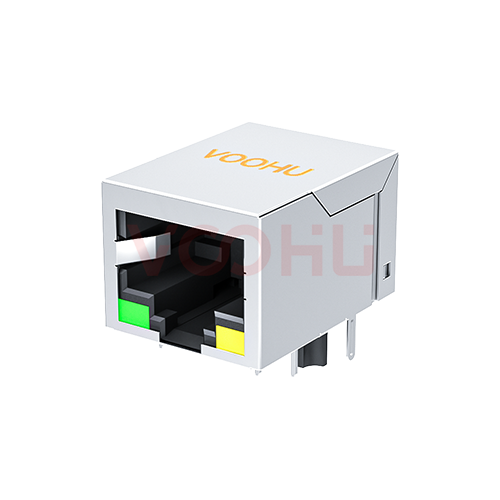
The VOOHU SYT111B002CA2A1D is a functional alternative to the LINK-PP LPJ0011BBNL — verify with samples in your design. Both are 1×1 tab-down 10/100 RJ45 jacks with integrated magnetics, green LED on the left and yellow on the right, and no EMI spring fingers. On one datum their hole positions match except the two LED rows, which sit 0.05 mm further forward on the VOOHU layout.
RJ45 MagJack pinout: do the LPJ0011BBNL and SYT111B002CA2A1D use the same pins?
Yes, by function. Both put TD+ on 1, TD− on 2, RD+ on 3, the center taps on 4 and 5, RD− on 6 and GND on 8, with pin 7 not connected. LED pins are 9 and 10 for green and 12 and 11 for yellow, anodes on 9 and 12, on both drawings.
RJ45 drill size: which hole diameters should a new layout for the SYT111B002CA2A1D use?
The VOOHU drawing recommends Ø0.89 mm for the signal pins, Ø1.02 mm for the LEDs, Ø3.20 mm for the locating posts and Ø1.63 mm for the shield pins. The LPJ0011BBNL drawing gives Ø0.9, Ø1.02, Ø3.25 and Ø1.7 mm. Neither says whether these are drilled or finished sizes, so state that in your fabrication notes.
RJ45 shield pin: do the shield pins land in the same place?
Yes. On both drawings the two shield pins are 15.75 mm apart and 3.05 mm behind the line through the locating posts. The recommended hole is Ø1.7 mm on the LINK-PP layout and Ø1.63 mm on the VOOHU layout, so on an existing board inspect the shield-pin joints on the first wave-soldered boards.
#Request SYT111B002CA2A1D samples for a fit trial
The quickest way to close this swap is a dry fit and a short solder run on the board you already have. When you request SYT111B002CA2A1D samples, attach the drill table for the jack area of your LPJ0011BBNL board and note whether its sizes are drilled or finished. Samples are available for evaluation, and selected parts are free of charge. Our FAE team will be glad to confirm the options for your project. Our FAE team can suggest suitable parts and help check the design — for this pair, overlaying your hole pattern on the VOOHU layout, checking what LED lead data is available for the 0.05 mm row shift, and the wave-solder settings for the first build. VOOHU supplies RJ45 and SFP connectors, LAN and PoE transformers and common mode chokes from Suzhou, China, to more than 1,500 customers.
For other LED, latch and port options, browse our RJ45 jacks.
Related product: SYT111B002CA2A1D, the 1×1 tab-down RJ45 jack with integrated 10/100 magnetics compared above: green and yellow LEDs, no EMI fingers, a 15.94 × 13.30 mm front face, 350 µH minimum OCL at 8 mA DC, −1.0 dB maximum insertion loss from 1 to 100 MHz, 1500 V AC and 2250 V DC hipot for 6 s at 1 mA, and a −40 to +85 °C operating range.
#Sources
- LINK-PP LPJ0011BBNL, RJ45 connector with 10/100 Base-T integrated magnetics, without EMI spring finger, with LED; drawing LP08071726, Rev. A (2008-07-17), sheets 1–2.
- VOOHU SYT111B002CA2A1D datasheet (TAB-DOWN 1X1 100BASE), Rev. A0, sheets 1–3.
Need a quote, samples or selection support?
Part number SYT111B002CA2A1D is filled in for you. Add the quantity and lead time and submit. Our FAE team will be glad to confirm the options for your project.
Before you order: samples, MOQ, lead time and import duties in our ordering guide →