The QSFP cage dimensions that matter for PCB layout come from the drawing of the exact cage, and they fall into four checks. First, the hole pattern: a 1×1 cage sits on a pattern of ø1.05 mm finished holes for its tails, with the host connector laid out inside the footprint, while 2×1 and 2×2 cage-and-connector assemblies add 76 signal holes of ø0.37 mm for the built-in connector. Second, board thickness, which each drawing states separately for single-sided and belly-to-belly mounting. Third, the bezel cutout: VOOHU 1×1 QSFP28 and QSFP-DD drawings dimension the opening at 20.00 ±0.10 mm and 10.15 ±0.10 mm, with its bottom edge 0.15 ±0.10 mm from the top of the board. Fourth, the heat sink height with a module plugged in. VOOHU drawings give each of these values, and several product pages offer STEP models for an enclosure fit check.
This checklist starts after the form factor is chosen; to choose one, see QSFP28 vs QSFP-DD vs QSFP112 cages, and for SFP ports the SFP cage PCB layout checklist. Every QSFP cage number below is copied from the VOOHU drawing of the part named next to it, so do not carry a value from one drawing to another.
#What does a QSFP cage footprint include?
A QSFP footprint has two groups of features that share one datum: the plated through-holes for the cage tails, and the contact field of the host connector, with 38 contacts on QSFP28, QSFP56 and QSFP112 and 76 on QSFP-DD. A 1×1 or 1×4 cage is sold without its connector, while a 2×1 or 2×2 assembly carries the connector inside, so its signal pins go into holes instead of surface pads.
The table lists the footprint data on six VOOHU drawings. Tolerances are as printed on each drawing.
Two details on these drawings are easy to miss. The WH591H009D1S20 drawing gives both a drilled hole of ø1.15 ±0.02 mm and a finished hole of ø1.05 ±0.05 mm after plating, with a table covering HASL, immersion tin, OSP and ENIG board finishes. Give your fabricator the finished size and tolerance: for press-fit tails the plated hole, not the drill, sets the retention. The same drawing measures its layout from the center of the compliant pin holes and refers to SFF-8662 for the connector pads, and it lists SFF-8663 as its product specification. When the connector field is not on the cage drawing, take the pads from the drawing of the connector you actually use and place them on the same datum as the cage holes. The SFF documents are listed by SNIA.
#Is a QSFP cage press-fit or soldered?
It depends on the part, so read the termination off the drawing rather than assuming it from the family. On the VOOHU drawings:
- Press-fit, called out as "compliant tails": the QSFP28 2×1 WHSFP38221F014 (compliant tails with 0.5 µm minimum tin over nickel) and the QSFP+ 2×1 WHSFP28221F013 (needle-eye contacts, 0.5–2.54 µm matte tin over 1.27–5.08 µm nickel). The QSFP56 2×2 WH81161Y22121 calls out compliant tails on the cage with a tail height of 2.0 mm, and signal tails of 1.2 mm.
- Soldered: the separate QSFP-DD connector WH81177C00021, with matte tin solder tails and two ø3.00 mm solder pads that hold the housing, and the QSFP112 connector WHSFP51311D002, with solder pads.
On a board that combines a soldered connector with a press-fit cage, the connector is reflowed first and the cage is pressed in afterwards, because a press-fit joint needs no solder. Plan the press step and its tooling with your assembly house before you fix component placement around the port.
#How thick should the board be, and can QSFP cages go belly to belly?
Belly-to-belly means mirrored ports on the top and bottom of the same board, and several VOOHU drawings include a separate layout for it. Each drawing sets its own minimum board thickness:
The minimum belly-to-belly thickness differs between drawings in the same family, so take it from your exact part. The double-sided pattern is a different footprint, too: the hole count goes from 11 to 22 on the WH591H009D1S20 and from 29 to 53 on the WH81177004331.
Board thickness also moves the front panel. The WH81177004331 drawing notes that PCB thickness variation must be considered when determining the bezel opening location. On a belly-to-belly board the bottom ports hang below the board, so the real board thickness, including the fabricator's tolerance, sets where their openings fall. Use the thickness you will actually order, not just the nominal value, when you draw the panel.
#What size is the QSFP bezel cutout, and how thick can the panel be?
The cutout, the panel thickness and the height of the opening above the board work together so that the cage's EMI spring fingers touch the panel around the opening. Copy all three from the same drawing:
Each cutout is dimensioned on the drawing view, so take its orientation from the view rather than from a table.
The spring fingers that close the gap belong to the cage: beryllium copper, 0.06 mm (REF), nickel plated on the WHSFP38221F014; stainless steel on the WH591H009D1S20 and the WH81177004331; and a nickel-plated copper alloy spring on the WH81161Y22121. Keep the panel surface where the fingers land conductive, with no paint or powder coat there, or the shield stays open at the cutout. Where the drawing gives no panel thickness, send your panel drawing to our FAE team and they will check the finger contact for the cage you choose.
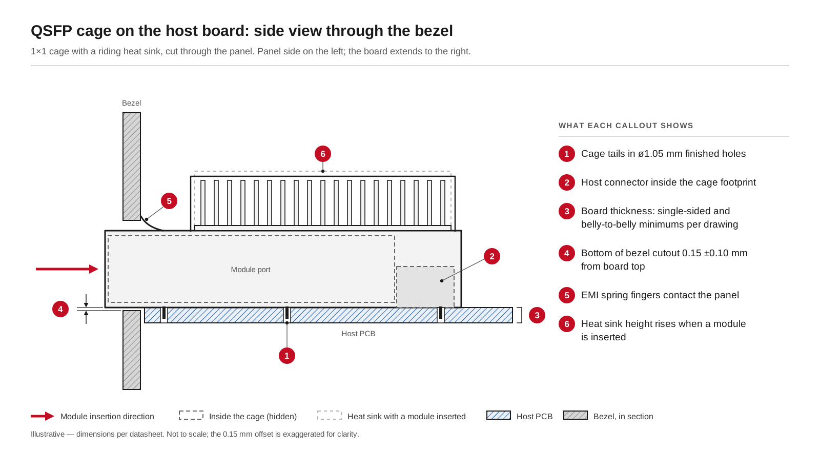
Side view of a 1×1 QSFP cage on the host board: cage tails in ø1.05 mm finished holes, the host connector inside the footprint, the bezel cutout 0.15 ±0.10 mm from the board top, EMI spring fingers against the panel and a riding heat sink. Schematic for illustration; dimensions per each VOOHU drawing.
#Does a QSFP cage need a heatsink, and how tall does it get?
Whether a port needs a heat sink is set by the module power and the airflow in your system. What the cage drawing tells you is the space the heat sink takes, and with a riding heat sink that height changes once a module is inserted:
Use the plugged-in figure for the lid clearance and for anything that sits above the ports, such as a second board or a cable tray. Light pipes need their own holes in the panel, as the WH591H009D1S20 bezel drawing shows. For airflow and module temperature checks, the approach in our SFP module overheating guide applies to QSFP ports as well.
#1×N ganged or 2×N stacked: what changes on the board?
A ganged 1×4 cage such as the WH81177004331 is one part with one footprint and one cutout of 77.00 ±0.1 mm across all four ports. Lay it out from its own drawing; four 1×1 footprints placed side by side will not match its hole pattern. Like a 1×1 cage, it needs a separate host connector at each port.
A stacked 2×1 or 2×2 assembly, such as the WHSFP38221F014 or the WH81161Y22121, has the connector built in, so the signal pins go into 76 holes of ø0.37 mm instead of onto surface pads, and the whole port block goes on the board as one part. Its cutout is taller, 25.70 mm on both drawings, and its lower port sits close to the board, with the bottom of the opening 0.1 mm from the board top. On the 2×2, a middle heat sink between the rows brings the plugged-in height to 29.0 mm.
Reference designTOR / Leaf Switch Reference DesignAn illustrative TOR / Leaf switch reference design for the…View solution →#Which VOOHU QSFP cage fits your board?
- WH591H009D1S20: QSFP28 1×1 cage with heat sink and quad light pipes; single-sided and belly-to-belly layouts, drilled and finished hole sizes, bezel cutout and board thickness all on the drawing.
- WH81177004331: QSFP-DD 1×4 ganged cage with heat sinks; single-sided and belly-to-belly panel designs, panel thickness annotated 1.60 ±0.80 mm, 14.4 mm max with modules plugged in.
- WHSFP38221F014: QSFP28 2×1 cage and connector assembly with compliant tails, 76 ø0.37 mm signal holes and a recommended panel cutout.
- WH81161Y22121: QSFP56 2×2 cage and connector assembly with compliant cage tails, top and middle heat sinks, light pipes and a 0.6–2.6 mm panel range.
For separate connectors, the QSFP-DD WH81177C00021 has 76 solder pads, and the QSFP112 WHSFP51311D002 has 38. Compare every part in the QSFP28 cage selector, the QSFP-DD cage selector and the QSFP56 selector, and see the QSFP112 connector page for that form factor.
The product pages of the WH591H009D1S20, WH81177004331, WH81161Y22121 and WH81177C00021 offer a STEP 3D model, so your mechanical team can check the cage, heat sink height and panel cutout in the enclosure model before samples arrive.
#FAQ
Does a QSFP cage need a separate connector?
A 1×1 or 1×N ganged QSFP cage does: it is the metal housing, and a host connector is mounted on the board inside its footprint. A 2×1 or 2×2 cage-and-connector assembly has the connector built in and goes on as one part. When you choose a separate cage, our FAE team confirms the connector that matches it.
What changes when an SFP port is moved to QSFP?
Almost everything on the board side. The connector goes from 20 contacts to 38, or 76 for QSFP-DD, and the cage holes, bezel cutout and panel position all change; a riding heat sink also adds height. Start a new footprint from the QSFP cage drawing rather than adapting the SFP footprint.
What is the difference between SFP and QSFP?
SFP is a single-channel port with a 20-contact host connector. QSFP is a four-lane port with a 38-contact connector in a wider cage, and QSFP-DD doubles that to eight lanes and 76 contacts in the same opening. Each needs its own cage, connector footprint and bezel cutout.
Are QSFP and QSFP+ the same?
They share the same form factor. QSFP+ is the 40G generation of QSFP, built on four lanes, and QSFP28 and QSFP56 keep the same 38-contact layout at higher lane rates; QSFP28 cages accept QSFP+ modules. Which generation to design for is covered in QSFP28 vs QSFP-DD vs QSFP112 cages.
Get QSFP cage and connector samples for your layout
Send us your port layout (1×1, 1×4, 2×1 or 2×2, single-sided or belly-to-belly), board thickness, panel thickness and the module types you plan to support through our sample request form. We quote the cage and connector as a set, and our FAE team confirms the matching connector part. Our FAE team can suggest suitable parts and help check the design, from the hole pattern and board thickness to the bezel cutout and heat sink clearance. Samples are available for evaluation, and selected parts are free of charge. Our FAE team will be glad to confirm the options for your project. VOOHU supplies RJ45 and SFP connectors, LAN and PoE transformers and common mode chokes from Suzhou, China, to more than 1,500 customers.
Need a quote, samples or selection support?
Part number WH591H009D1S20 is filled in for you. Add the quantity and lead time and submit. Our FAE team will be glad to confirm the options for your project.
Before you order: samples, MOQ, lead time and import duties in our ordering guide →