An RJ45 MagJack datasheet is two documents on the same sheets: a LAN transformer datasheet and a connector drawing. A MagJack (RJ45 jack with integrated magnetics) puts the transformers, common-mode chokes and termination inside the jack, so read its datasheet in three passes. First, the electrical lines, such as turns ratio, OCL, insertion and return loss, crosstalk, common-mode rejection and Hi-Pot, each with its test condition. Second, the lines only an integrated jack carries: the internal schematic with its center taps and termination, the PoE current, the LED table, contact plating, shield, mating cycles and soldering profile. Third, the lines that are not there, because a missing line is an open question, not a pass. Below, two VOOHU datasheets are read line by line: one Gigabit PoE jack with LEDs, and one 10/100 jack without either.

For what each transformer line means, see how to read an Ethernet transformer datasheet; for pin numbering, see the RJ45 jack pinout with integrated magnetics. This page covers what an RJ45 jack datasheet adds once the magnetics are inside.
#What is in an RJ45 connector specification PDF with integrated magnetics?
The two examples are the SYT411Q199DB2A1DP, a 1×1 tab-up Gigabit PoE jack with LEDs, and the SYT112B083HWA1D5, a 1×2 tab-down 10/100 jack without PoE or LEDs. Both datasheets run to three sheets, laid out as in the figure, and every sheet carries the REACH and RoHS statement.
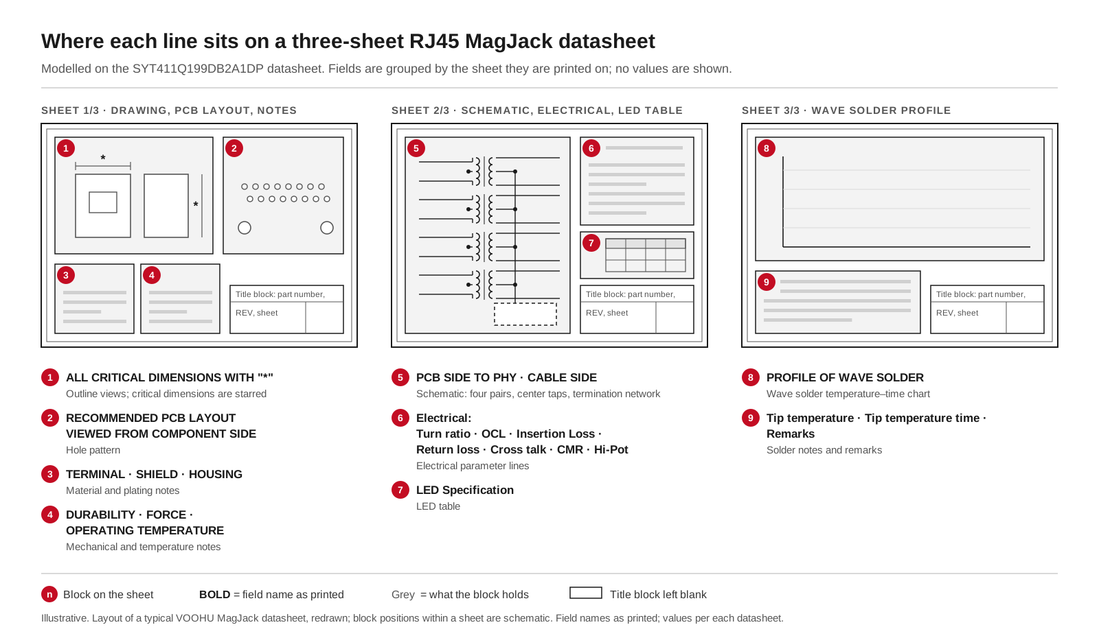
Where each line sits on a three-sheet VOOHU MagJack datasheet: drawing, PCB layout and materials on sheet 1; schematic, electrical lines and LED table on sheet 2; wave solder profile on sheet 3. Redrawn for illustration; field names as printed, values per each datasheet.
The table puts both datasheets side by side. Values and test conditions are as printed.
#How do you read a MagJack schematic?
The schematic tells you what is inside the jack and which pins your board has to handle. On the SYT411Q199DB2A1DP, the side marked "PCB side to PHY" has four pairs, TD1± to TD4±, with their center taps on pins 12, 6, 1 and 7. Each pair passes a common-mode choke and a 1CT:1 transformer to the cable side, J1 to J8. The cable-side center taps come out on pins 13 to 16 (VC1 to VC4) for PoE, and each one also runs through a 12 nF/100 V capacitor and a 75 Ω resistor to a common 1000 pF/2 kV capacitor tied to the shield. The 12 nF capacitors keep the PoE DC out of the termination network; they are rated 100 V, and the PoE line on the same datasheet is stated at 57 V DC.
The SYT112B083HWA1D5 is drawn for 10/100: TD± on pins 1 and 3 with the center tap on pin 2, and RD± on pins 4 and 6 with the center tap on pin 5, each 1CT:1, and the common-mode chokes on the cable side. Its four 75 Ω resistors return through one 1000 pF/2 kV capacitor to GND on pin 8. Three checks follow from any MagJack schematic:
- PHY-side center taps. How they connect depends on the PHY, so take it from the PHY vendor's reference schematic; see connecting a LAN transformer to the PHY.
- Termination already inside. The 75 Ω network is in the jack, so do not add a second one on the board.
- Where the termination returns. To the shield on the SYT411Q199DB2A1DP, to pin 8 on the SYT112B083HWA1D5, so on the second part your pin 8 connection decides it. Tie it into your chassis ground plan on purpose.
#Which electrical lines read the same as a LAN transformer datasheet?
These lines, from turns ratio to common-mode rejection, describe the magnetics that isolate the cable and reject common-mode noise, and they read exactly as on a discrete transformer. When you compare two MagJacks, the test condition decides whether two numbers mean the same thing. The SYT411Q199DB2A1DP measures OCL with 15 mA of DC bias, the SYT112B083HWA1D5 with 8 mA, so compare suppliers at the same bias. Read the band edges too: return loss on both is specified to 80 MHz, the other loss lines to 100 MHz, and the same dB figure over a narrower band is not the same specification.
Read the Hi-Pot line in four parts: the voltage and whether it is AC or DC, the time, the leakage limit, and the points it is applied between. The SYT411Q199DB2A1DP lists 2250 V DC for 6 s at 1 mA, primary to secondary, and its notes state that 100% of production is tested to comply with the IEEE 802.3 isolation requirements. The SYT112B083HWA1D5 lists 1500 V AC and 2250 V DC under the same time and limit. An AC figure and a DC figure are different tests, so compare like with like. If your safety plan names a specific form or duration, our FAE team will confirm the test for the part; see why an Ethernet port fails a Hi-Pot test for the system side.
#How do you read the PoE line on a MagJack datasheet?
A PoE MagJack brings its cable-side center taps out to pins so the power circuit can reach the pairs; on the SYT411Q199DB2A1DP these are pins 13 to 16. Its current line reads "balanced DC line current 720mA max. @57V DC continuous". The line does not say whether the 720 mA applies per pair or per port, so do not divide or multiply it to fit your power budget; ask our FAE team to confirm the scope for your port. To match the current to a PoE type, see PoE RJ45 connector selection. The SYT112B083HWA1D5 has no PoE line and no cable-side center-tap pins, so treat it as a data-only jack.
#LED, plating, shield and mating cycles: the connector lines
The contact line is the same on both: phosphor bronze C5210 terminals, 0.35 mm thick, with 6U" gold on the contact area. 6U" means 6 microinches, about 0.15 µm, so check the unit and where the gold is before you compare two jacks; RJ45 gold plating, 3U vs 6U vs 50U explains what thickness changes. Both datasheets state 750 mating cycles minimum and 23 N maximum mating force. They do not tie these figures to a standard, so do not add one when you copy them into your specification.
The LED table on the SYT411Q199DB2A1DP gives green at 568 nm and yellow at 585 nm, both at 20 mA, with forward voltages of 1.85–2.45 V and 1.7–2.2 V; green sits on the left on pins 20/19, yellow on the right on pins 18/17. Size the series resistor from your PHY's LED drive and this range, then check polarity as in how to check RJ45 LED polarity. The SYT112B083HWA1D5 has no LEDs, so link indicators would have to sit on the board. Both have a C2680 shield, 0.20 mm and nickel plated all over. Neither datasheet names or specifies EMI fingers or a gasket, although the outline views draw tabs on the shield; if your panel relies on fingers that touch the bezel, ask our FAE team to confirm the grounding for your panel.
The footprint sits on sheet 1 under "recommended PCB layout viewed from component side": 16 holes of ø0.89 mm and two of ø3.20 mm on both parts; the SYT411Q199DB2A1DP adds four ø1.14 mm holes for its LED pins and two of ø1.57 mm, and the SYT112B083HWA1D5 three of ø1.63 mm. Dimensions marked with an asterisk are the critical ones. Sheet 3 gives a wave solder profile: 260 ±5 °C for 5 s maximum, with Sn96.5/Ag3/Cu0.5 solder melting at 217 °C, and a remark that the plastic locating posts under the board may melt slightly without affecting function. Both datasheets give a wave profile only, so if you plan to reflow the jack, ask for the reflow limits before you set the process.
SolutionEthernetInterface + magneticsView solution →#How do you compare two MagJack datasheets when qualifying an alternative?
Go through the lines in the order that would stop a design, and compare each at the same condition:
- 1.Data rate, pair count and center-tap arrangement in the schematic.
- 2.PoE pins and the PoE current with its stated scope.
- 3.OCL at the same DC bias; loss lines over the same bands.
- 4.Hi-Pot form, voltage, time and test points.
- 5.Footprint holes, the viewing side of the layout and the critical dimensions.
- 6.LED colors, positions and pins; tab direction.
- 7.Plating, mating cycles, soldering process and temperature range.
For the wider choice of an integrated jack against a discrete transformer, see integrated or discrete RJ45 connectors.
Then list the lines that are not on either datasheet. Neither example states an MSL or a reflow profile, insulation resistance, leakage inductance, interwinding capacitance, DC resistance, a PoE Type or Class number, an EMI finger or gasket specification, contact resistance or a contact current rating. A missing line is neither a pass nor a fail. Write down the lines your design or your incoming inspection depends on, ask for the missing ones before you approve the part, and send the list to our FAE team, who will confirm what is available for the VOOHU part you pick.
To find a VOOHU jack with the lines you need, filter the RJ45 selector by integrated magnetics, then narrow it by PoE, LED and tab direction. Every row links to its datasheet, and the product pages of the SYT411Q199DB2A1DP and SYT112B083HWA1D5 hold the two datasheets read on this page.
#FAQ
What is a MagJack?
MagJack is a common name for an RJ45 jack with integrated magnetics: the Ethernet transformers, common-mode chokes and termination sit inside the jack, so the PHY pairs connect straight to the jack pins. Its datasheet combines transformer lines such as OCL and Hi-Pot with connector lines such as plating and mating cycles.
How many mating cycles is an RJ45 jack rated for?
As many as its datasheet states, as a minimum. Both VOOHU examples here state 750 cycles minimum, with 23 N maximum mating force and 6U" gold on the contact area. Compare that with how often the port will be plugged in service, and read the plating line with it, because the contact gold is what wears with each cycle.
Where is the pinout in a MagJack datasheet?
In two places. The schematic gives each pin's function, such as TD1+ or a center tap, and the recommended PCB layout gives each pin's position, viewed from the component side on the VOOHU examples. Build the footprint from both, and see the RJ45 jack pinout with integrated magnetics for pin 1 on tab-up and tab-down jacks.
How do I use a Gigabit Ethernet jack with integrated magnetics with my PHY?
Connect the PHY's four MDI pairs to the jack's PHY-side pairs by the schematic pin numbers, TD1± to TD4± on the SYT411Q199DB2A1DP. Handle the PHY-side center taps as the PHY reference design shows, and do not add a second termination on the board. Our FAE team can check the connection against your PHY.
Get a MagJack checked against your datasheet lines
Send us the lines your design depends on, such as PoE current, LED colors, Hi-Pot requirement and footprint, through our sample request form. Our FAE team can suggest suitable parts and help check the design, from the center-tap connection and the scope of the PoE current to the LED pins and the footprint. Samples are available for evaluation, and selected parts are free of charge. Our FAE team will be glad to confirm the options for your project. VOOHU supplies RJ45 and SFP connectors, LAN and PoE transformers and common mode chokes from Suzhou, China, to more than 1,500 customers.
Need a quote, samples or selection support?
Part number SYT411Q199DB2A1DP is filled in for you. Add the quantity and lead time and submit. Our FAE team will be glad to confirm the options for your project.
Before you order: samples, MOQ, lead time and import duties in our ordering guide →