Compiled from both manufacturers' published datasheets. Verify with samples and the PCB footprint before production.
Channel by channel, the HanRun HY604808 and the VOOHU WHSG48001G use the same pin numbers and pin functions across all eight channels (HanRun labels the line-side pins MX and MCT, VOOHU labels them TX and CMT), yet their schematics take the line-side center tap from different places. HanRun brings MCT out of a separate center-tapped winding placed after the common mode choke; VOOHU brings CMT straight off the transformer's line-side winding and puts the choke after it. The WHSG48001G is still a functional alternative to the HY604808 — verify with samples in your design, and include an EMI pre-scan. Both are dual-port gigabit magnetics in 48-pin SMD packages on a 1.02 mm pitch, rated 0 to +70 °C, with 350 µH minimum OCL at 8 mA DC bias and a 1500 V, 60 s hipot. The second difference is the land pattern: outer pad edges 15.88 mm apart on the HanRun drawing (converted from 0.625 in) against 16.50 mm on the VOOHU drawing.
#HY604808 and WHSG48001G parameters from the two datasheets
How the table was built: the HanRun column is read from the HY604808 datasheet, REV A/3, a single distributor-hosted page that holds the electrical table, schematic, outline and recommended pad layout, all in inches. Millimetre values in brackets are converted at 25.4 mm per inch and rounded to two places. The VOOHU column is read from the WHSG48001G datasheet, revision A0, which is drawn in millimetres: outline, recommended pads and schematic on page 1, electrical items on page 2. A value marked calculated is worked out from printed dimensions and is not printed itself. Not stated means the document gives no value.
#Ethernet magnetics center tap connection: what pin 48 connects to on each part
Start on the cable side, because that is where the drawings diverge. On the HY604808, the chip-side winding of each channel has its center tap on TCT, pin 1 for channel 1, and the line-side winding of the same transformer has no tap. Its two ends go through a two-wire common mode choke, and only after the choke does a second, center-tapped winding sit across MX1+ on pin 47 and MX1− on pin 46. The midpoint of that winding is MCT1 on pin 48. HanRun marks the ratio 1CT:1, which matches a line-side winding without a tap. On the WHSG48001G the transformer is 1CT:1CT: its line-side winding carries its own center tap, wired directly to CMT1 on pin 48, and the two ends of that winding pass through the two-wire choke to TX1+ on pin 47 and TX1− on pin 46. The other seven channels repeat each pattern down to pins 26, 27 and 25. So pin 48 is the same pin with the same job on your schematic, but inside the package it lands on a different node: on the cable side of the choke in the HanRun part, on the transformer side of the choke in the VOOHU part.
#Bob Smith termination on an HY604808 board: same pins, different node
The termination itself does not move. Whatever your design hangs on MCT1 to MCT8, such as a Bob Smith termination, stays on pins 48 through 27, and no trace on the board needs to change. What changes is where that network meets the cable pairs. With the HY604808 it meets them on the cable side of the choke; with the WHSG48001G it meets them on the transformer side. That is a different common-mode path, and neither datasheet tells you what it does to emissions on your board. Their common mode lines cannot settle it either: HanRun prints a "Different to Common Mode Rejection" figure at three frequencies, VOOHU prints one common mode rejection minimum from 1 to 100 MHz, and both are limits written in different ways, not measurements of either part in your product. The way to find out is a pre-scan on real hardware.
Because this is a two-port part, scan it the way the product runs. Build one board with the HY604808 and one with WHSG48001G samples from the same PCB lot, keep the enclosure, cables and termination values unchanged, link both ports at 1000 Mb/s with traffic on each, and compare radiated emissions from 30 MHz to 1 GHz with the HanRun board as the baseline. If your certification plan also covers conducted emissions, ESD or surge on these ports, repeat those steps on the sample build rather than carrying the old results over, and leave both ports running long enough to read the error counters on your longest cable. One schematic task goes with it: if your symbol for the HY604808 draws the internal magnetics, that drawing no longer describes the part you are fitting. Update it, or attach the WHSG48001G page-1 schematic to the alternate entry, so whoever reviews the EMC results sees the topology that was actually tested. Our FAE team can suggest suitable parts and help check the design if the pre-scan shows a difference you want to talk through.
#HY604808 footprint in mm: 15.88 vs. 16.50 mm across the outer pad edges
HanRun dimensions the recommended pattern in inches, so start by converting it. The pads are 0.025 in wide (0.64 mm), the outer edges of the two rows are 0.625 in apart (15.88 mm) and the inner edges 0.490 in (12.45 mm), with 0.920 in (23.37 mm) from the first pad to the last. The drawing does not print a pad length; half the difference between the two edge dimensions gives 0.0675 in, or 1.71 mm (calculated). VOOHU recommends 0.64 mm pads, 1.90 mm long, with the outer edges 16.50 mm apart and 23.46 mm from the first pad to the last, which puts the inner edges 12.70 mm apart (calculated). Laid over each other on one center, the VOOHU pattern sits further out at both ends of each pad: about 0.31 mm per side at the outer edge and about 0.13 mm at the inner edge. Along the rows the end pads differ by 0.09 mm over 23.4 mm (all calculated).
For a board already built on HanRun pads, the useful question is where the WHSG48001G toes end up, and the answer depends on tolerance more than on nominal size. At its nominal 15.20 mm across the leads, the VOOHU toe sits about 0.34 mm inside each HanRun outer pad edge, close to the 0.32 mm the HY604808's own 15.24 mm lead span leaves. The VOOHU drawing allows ± 0.50 mm on that span, though, against ± 0.015 in (± 0.38 mm) on the HanRun drawing. At 15.70 mm, the top of the VOOHU range, the toe would sit about 0.09 mm inside the HanRun outer edge (all calculated, with the part centred on the pattern). So treat the existing board as a first-article trial: overlay the WHSG48001G outline at both 15.20 and 15.70 mm on your pads, then look at the toe fillets from the side on pins 1, 24, 25 and 48 and on a few middle pins. We have no written FAE confirmation yet for fitting the WHSG48001G to the HanRun pattern. For the next layout, build a separate WHSG48001G footprint from its page-1 pattern instead of editing the HY604808 one. Height is not a constraint in this direction: 7.50 mm maximum for VOOHU against 0.310 in (7.87 mm, converted) for HanRun, so clearance drawn for the HanRun part covers the VOOHU part. Only a move back to the HY604808 would need the 7.87 mm checked.
#Hipot leakage and the electrical lines on the inspection sheet
Incoming inspection needs a short edit rather than a new procedure. Both datasheets hipot at 1500 V for 60 s; HanRun fails a part above 0.5 mA, measured from pins 1–24 to pins 25–48, and VOOHU sets the criterion at 1 mA. Write the WHSG48001G line as 1500 VAC, 1 mA, 60 s, and if a customer or safety file holds you to 0.5 mA, ask us for written data at that limit before changing the tester. Our article on why an Ethernet port fails the Hi-Pot test explains the wider isolation path. The rest is copying: insertion loss −1.1 dB maximum, the return loss bands as VOOHU prints them, and the common mode and crosstalk lines in VOOHU's wording rather than mapped onto HanRun's frequencies. The VOOHU sheet also adds three lines the HanRun sheet does not have, 0.5 µH maximum leakage inductance, 1400 mΩ maximum DCR and a ± 5% turns ratio tolerance, so the sheet for the new part gets longer, not shorter.
#HY604808 to WHSG48001G: swap verification checklist
#Which designs the WHSG48001G suits
The WHSG48001G is meant for two copper gigabit ports sharing one 48-pin, 1.02 mm-pitch transformer, the usual dual port Ethernet transformer arrangement, in equipment that stays within 0 to +70 °C, the operating range printed on both datasheets. It fits most easily where the termination values are already set and the EMC margin is known, because the pre-scan then has a clear baseline to compare against. If other HanRun magnetics or jacks are on the same BOM, our HanRun cross reference lists the VOOHU parts we have compared so far.
SolutionEthernetInterface + magneticsView solution →#FAQ
What is an equivalent for the HanRun HY604808 48-pin dual-port gigabit transformer?
The VOOHU WHSG48001G is a functional alternative to the HanRun HY604808 — verify with samples in your design. Both are 48-pin SMD dual-port gigabit magnetics on a 1.02 mm pitch with the same pin numbers and pin functions, 350 µH minimum OCL at 8 mA DC bias, a 1500 V, 60 s hipot and a 0 to +70 °C rating. Their line-side center taps are built differently, so plan an EMI pre-scan, and compare the recommended pads before reusing a board.
How is the Ethernet magnetics center tap connection different on the HY604808 and the WHSG48001G?
The pin numbers and functions are the same: TCT on pins 1, 4 and so on to 22, MCT or CMT on pins 48 down to 27. Inside, the HY604808 takes MCT from a separate center-tapped winding after the common mode choke, while the WHSG48001G takes CMT straight from the transformer's line-side winding with the choke after it. No board wiring changes; the EMI result is what needs checking.
Does the Bob Smith termination have to change when the WHSG48001G replaces the HY604808?
Not on the board. The termination stays on the same MCT / CMT pins. Inside the package it connects at a different point relative to the common mode choke, so keep the values you have, run a radiated emission pre-scan against the HY604808 board, and adjust only if the scan gives you a reason to.
What is the HY604808 footprint in mm?
Converted from the HanRun drawing: pads 0.64 mm wide on a 1.02 mm pitch, outer edges 15.88 mm apart, inner edges 12.45 mm apart and 23.37 mm from the first pad to the last. The pad length, 1.71 mm, is calculated from the two edge dimensions because the drawing does not print it. The WHSG48001G pattern uses 0.64 × 1.90 mm pads with outer edges 16.50 mm apart.
Common mode choke vs. transformer: which is which on these two schematics?
On both, each of the eight channels has a transformer, which provides the isolation, and a two-wire common mode choke on the line side. The HY604808 adds a center-tapped winding after its choke to create MCT. The WHSG48001G takes the center tap from the transformer's own line-side winding. The ratio labels follow the drawings: 1CT:1CT on the VOOHU sheet, 1CT:1 on the HanRun schematic.
#Before you request WHSG48001G samples
A request that already includes your design gets a more useful answer. When you request WHSG48001G samples, send the schematic from the RJ45 jacks to the transformer with the termination on the MCT pins visible, the pad dimensions on your current HY604808 board, and, if you have one, the emissions report the HanRun build passed. Samples are available for evaluation, and selected parts are free of charge. Our FAE team will be glad to confirm the options for your project. Our FAE team can suggest suitable parts and help check the design — for this pair, how your termination sits on a center tap taken from the transformer winding rather than after the choke, what the pre-scan should be compared against, and how the toes land on your 15.88 mm HanRun pads.
VOOHU supplies RJ45 and SFP connectors, LAN and PoE transformers and common mode chokes from Suzhou, China, to more than 1,500 customers.
For other 48-pin parts on a 1.02 mm pitch, the LAN transformer selector opens with pin count and pitch already set.
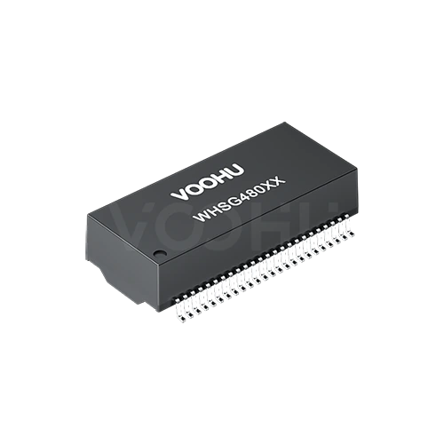
Related product: WHSG48001G. Two 100/1000BASE-T ports in one 48-lead SMD package on a 1.02 mm pitch, 27.80 × 12.20 mm and at most 7.50 mm tall. Each of the eight channels is a 1CT:1CT transformer whose line-side center tap goes straight to its CMT pin, with a two-wire common mode choke toward the cable. The datasheet gives 350 µH minimum OCL with 8 mA DC bias, 1400 mΩ maximum DCR, a 1500 VAC, 60 s hipot and 0 to +70 °C operation.
#Sources
- HanRun HY604808 1000Base-T Magnetic Module datasheet, REV A/3 (one page, distributor-hosted copy).
- VOOHU WHSG48001G datasheet, Rev. A0 (two pages).
Need a quote, samples or selection support?
Part number WHSG48001G is filled in for you. Add the quantity and lead time and submit. Our FAE team will be glad to confirm the options for your project.
Before you order: samples, MOQ, lead time and import duties in our ordering guide →