The UDE approval sheet for the SA10-KW-0001 gives a recommended panel cutout 15.45 ± 0.10 mm wide. The panel cutout on the VOOHU drawing for the WH81-111-00006-1 is 15.25 ± 0.10 mm wide, and both are 10.40 mm high. Apart from that, the two 1×1 solder-tail SFP cages line up closely: the WH81-111-00006-1 is a functional alternative to the SA10-KW-0001 — verify with samples in your design. Both drawings dimension the cage as 14.00 mm wide and 8.95 mm high (UDE dimensions both inside to inside), and the two recommended PCB layouts call for the same hole count, hole diameters and SMT pads. Both are rated −40 to +85 °C operating. So the board is the smaller question in this change. The front panel, and the way the EMI fingers meet it, is where the evaluation time should go.
#SA10-KW-0001 vs. WH81-111-00006-1: approval sheet and datasheet values
UDE documents this cage in approval sheet SA1022008-00, revision C, dated 2023-07-28: eight pages covering the outline, the recommended PCB layout, the recommended panel cutout, materials, ratings and a wave-solder profile. VOOHU documents the WH81-111-00006-1 in a two-page datasheet, revision A0, titled SFP 1x1 CAGE SOLDER TAIL. Page references below are PDF pages. Dimensions are in millimetres and copied as printed. A value marked REF is a reference dimension, which neither drawing tolerances. A cell reading "not stated" means the document does not cover that item.
#SFP cage footprint: same hole count and pads, different panel opening
A 1×1 SFP cage has two interfaces with the product, and they are drawn on separate sheets. The PCB layout governs the tails, the SMT pads for the host connector and the keep-out areas; on both drawings those items carry the same hole count, diameters, pad sizes and outline dimensions. The panel cutout governs how the front of the cage, with its ring of EMI fingers, sits in the bezel, and each supplier sizes that opening around its own finger design. Two cages can therefore share board features and still call for different panel openings. One caution on the board side: the two layouts are dimensioned from different datums, so overlay the VOOHU page 2 layout on your existing footprint before releasing a board. Our SFP cage PCB layout guide covers the board side in more depth.
#UDE SFP cage panel cutout vs. the VOOHU drawing: the tolerance stack
Work the printed tolerances through and the two widths barely touch. UDE's 15.45 ± 0.10 mm allows 15.35 to 15.55 mm; the 15.25 ± 0.10 mm on the VOOHU drawing allows 15.15 to 15.35 mm. These ranges are calculated from the printed values, and the only width inside both is 15.35 mm. At nominal, an opening cut to the UDE figure is 0.20 mm wider than the VOOHU figure. The height is 10.40 mm on both, and both limit the corner radius to 0.3 mm.
For the mechanical engineer, the decision depends on whether the panel already exists. If it is tooled or punched to the UDE drawing, do not recut it on paper: fit WH81-111-00006-1 samples into production panels and inspect the fingers around the full opening, with and without a module inserted. If the panel is still being drawn and both cages are meant to be approved for it, choose the cutout width deliberately and validate it with samples of both. A value copied from either sheet sits at the edge of the other's range.
Two other panel lines deserve a look. On a panel with several 1×1 openings side by side, UDE asks for at least 0.80 mm between cutouts, which with a 15.45 mm opening works out to a centre spacing of at least 16.25 mm. That is calculated, and it equals the 16.25 mm minimum printed on the VOOHU drawing, so port spacing does not change. The vertical reference is described differently: UDE gives 0.39 ± 0.10 mm as the bezel opening below the PCB, while VOOHU gives 0.40 ± 0.10 mm from the top of the PCB to the inside of the cutout. Check which surface your panel drawing measures from before treating the two figures as the same dimension.
#SFP cage grounding at the bezel: what the EMI finger figures tell you
The fingers are what ground the cage to the panel at the opening, so the EMC engineer will want to compare them. The drawings do not allow a clean comparison. UDE prints 16.00 mm REF across the fingers and labels it uncompressed. VOOHU prints 15.80 mm REF across the same area without saying whether the fingers are free or compressed. With different definitions and no tolerance on either, subtracting one from the other does not give you an interference figure, and the cutout difference above cannot be translated into "more" or "less" finger contact from the drawings alone.
That leaves a physical check. Build one unit with VOOHU cages in the production panel, with the panel's real thickness and surface finish. With a module seated, confirm that the fingers bear on the cutout edge all the way round. Then run a radiated-emissions pre-scan with the SFP port in use and compare it with the same unit built with UDE cages. Do this before the formal EMC test, because a panel change found at that stage costs far more than a sample build. If the result is marginal, ask our FAE team how the 15.80 mm figure is defined and what finger deflection the cage is designed for.
#Tail length, temperature and insertion force: the remaining lines
For Layout and the EMS partner, the tails are 3.10 mm below the board on the UDE drawing and 3.02 mm on the VOOHU drawing, 0.08 mm shorter by subtraction. On a thick board, look at the first boards from the wave line and confirm the solder fill your workmanship standard asks for. Temperature needs no action, since the operating (−40 to +85 °C) and storage (−55 to +105 °C) lines match. Insertion force, extraction force, cage retention and durability appear only on the UDE sheet. If a reliability plan or incoming check quotes 18 N, 12.5 N, 90 N or 100 cycles, the VOOHU datasheet has no line to put next to them. Ask our FAE team for the figures, or measure them on samples.
#Validation order for an SA10-KW-0001 to WH81-111-00006-1 change
Panel first, because it is the most expensive part to change; the board last, because it is the least likely to need changing.
#Where the WH81-111-00006-1 fits as an SA10-KW-0001 alternative
The easiest fit is a new product whose front panel is not yet released, where the cutout can be set and proven with both cages from the start. The common case is an existing product with one or more 1×1 solder-tail SFP ports, a panel already cut to the UDE drawing and a BOM that needs a second cage source. That works once samples pass the panel fit and EMC pre-scan in the table above. Products with a reliability plan built on UDE's insertion and retention figures need the VOOHU data first.
#FAQ
Which SFP cage can replace the UDE SA10-KW-0001?
The VOOHU WH81-111-00006-1 is a functional alternative to the UDE SA10-KW-0001 — verify with samples in your design. The two share the 1×1 solder-tail format, the 14.00 mm width and 8.95 mm height dimensions, and a −40 to +85 °C operating range. What differs is the panel opening each drawing gives, so check finger contact in your own panel before approval.
What panel cutout does the UDE SA10-KW-0001 use?
UDE approval sheet SA1022008-00 recommends 15.45 ± 0.10 × 10.40 ± 0.10 mm for single-side mounting with spring fingers, with at least 0.80 mm between adjacent cutouts. The panel cutout on the VOOHU drawing for the WH81-111-00006-1 is 15.25 ± 0.10 × 10.4 ± 0.10 mm.
What are the SA10-KW-0001 SFP cage dimensions?
On UDE approval sheet SA1022008-00 revision C, the cage is 14.00 ± 0.10 mm wide and 8.95 ± 0.15 mm high, both measured inside to inside. It is 16.00 mm REF across the uncompressed EMI fingers, and its tails extend 3.10 mm below the board.
Can an SA10-KW-0001 PCB footprint be used for the WH81-111-00006-1?
It is a reasonable starting point. Both recommended layouts list ten Ø1.05 mm tail holes, nine Ø0.95 mm and one Ø0.85 mm connector-area holes, two Ø1.55 mm locating holes and 20 SMT pads on a 0.80 mm pitch. The drawings use different datums, so overlay them and build samples before release.
#Send your panel drawing with the sample request
To request WH81-111-00006-1 samples, include the front-panel drawing with the cutout width, height and tolerances, the panel thickness and material, and the number of SFP openings. If the product has a radiated-emissions limit that the SFP port has to meet, say which. Samples are available for evaluation, and selected parts are free of charge. Our FAE team will be glad to confirm the options for your project. Our FAE team can suggest suitable parts and help check the design — for this cage, comparing your existing cutout with the VOOHU drawing, explaining how the finger width is defined and checking what insertion and retention data is available for your plan.
VOOHU supplies RJ45 and SFP connectors, LAN and PoE transformers and common mode chokes from Suzhou, China, to more than 1,500 customers.
Other 1×1 and ganged cages are listed in the SFP connector selector, which opens filtered to cages.
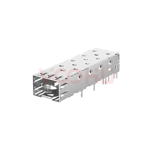
Related product: WH81-111-00006-1 — 1×1 SFP cage, solder tails, no light pipe, 14.00 × 8.95 mm cage opening, −40 to +85 °C operating.
#Sources
- UDE approval sheet SA1022008-00, SA10-KW-0001 SFP Cage 1X1, Rev. C, 2023-07-28 (8 pages)
- VOOHU WH81-111-00006-1 datasheet, Rev. A0 (2 pages)
Need a quote, samples or selection support?
Part number WH81111000061 is filled in for you. Add the quantity and lead time and submit. Our FAE team will be glad to confirm the options for your project.
Before you order: samples, MOQ, lead time and import duties in our ordering guide →